Parameters
| MASTERID | Contains the axis ID of the host/master where the drive/motor must send the PVT messages. It must be set before starting the PVT mode. The MASTERID value must be set as: host ID << 4 + 1, where host ID is a number between 1 and 255 representing the host ID. By default, after power-on the host ID is set equal with the drive address causing all the PVT messages to be sent via RS-232 |
| PVTBUFBEGIN | Specifies the start address of the PVT buffer |
| PVTBUFLEN | Specifies the PVT buffer length expressed in PVT points |
| PVTPOS0 | Specifies for absolute mode, the initial position from which to start computing the distance to move up to the first PVT point. An alternate option is to consider TPOS as initial position. Selection between these 2 options is done at PVT initialization via TML command SETPVT. The default value of PVTPOS0 is 0. |
| PVTSENDOFF | When set to 1, disables transmission of messages during PVT mode. By default is set to 0 and the transmission is enabled |
Variables
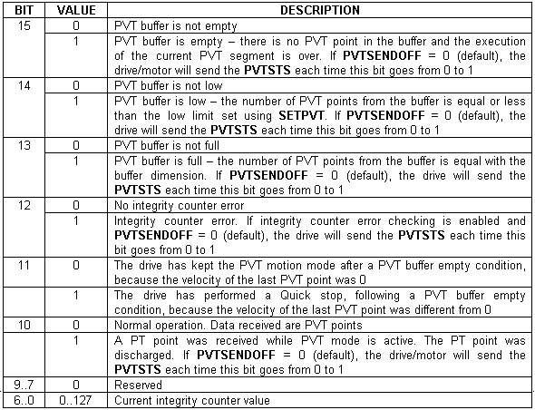
PVTSTS Contains the PVT motion mode status.
PVTSTS bit description
| PVTMODE | PVT operation mode as was set with the SETPVT command |
| TPOS | Target load position – position reference computed by the reference generator at each slow loop sampling period. Measured in position units |
| TSPD | Target load speed – speed reference computed by the reference generator at each slow loop sampling period. Measured in speed units |
| TACC | Target load acceleration – acceleration/deceleration reference computed by the reference generator at each slow loop sampling period. Measured in acceleration units |
APOS_LD Actual load position. Measured in position units. Alternate name: APOS
ASPD_LD Actual load speed – measured in speed units
APOS_MT Actual motor position. Measured in motor position units.
ASPD_MT Actual motor speed. Measured in motor speed units. Alternate name: ASPD
Instructions
SETPVT value Set PVT operation as specified by value:
PVT operation mode (a copy of value is saved in the TML variable PVTMODE)
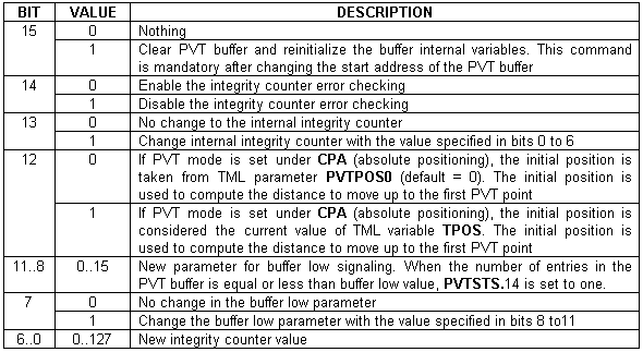
CPR PVT mode is relative
CPA PVT mode is absolute
MODE PVT Set PVT motion mode.
| TUM1 | Target Update Mode 1 (TUM1). Generates new trajectory starting from the actual values of position and speed reference (i.e. don’t update the reference values with load/motor position and speed) |
| TUM0 | Target Update Mode 0 (TUM0). Generates new trajectory starting from the actual values of load/motor position and speed (i.e. update the reference values with load/motor position and speed) |
PVTP Position, Velocity, Time, Counter Defines a PVT point, where:
Position – is the PVT point position, measured in position units. In absolute mode, it is the position to reach. In relative mode, it is the position increment from the previous PVT point. The position value is a signed long integer limited to 24 bits, i.e. in the range – 8388608 to + 8388607. Values outside this range are truncated causing unpredictable results.
Velocity – is the PVT point velocity, measured in speed units. The velocity is a fixed value like command speed CSPD and target speed TSPD
Time – is the PVT point time measured in time unitsHELP_INTERNAL_UNITS@kernel.hlp. The time value is a 9-bit unsigned integer having values between 1 and 511.
Counter – is the PVT point integrity counter. It is a 7-bit unsigned integer with values between 0 and 127.
UPD Update motion parameters and start new motion mode
STOP Stop the motion
Remarks:
| • | When a PVT sequence of points is executed from a TML program, the first PVTP commands are processed one after the other, until the PVT buffer fills up. At this point the TML program stops until the PVT buffer starts to empty. Therefore, the next PVTP commands are processed in the cadence of the PVT points execution. At the end of the sequence, the PVT buffer starts to empty and next TML instructions start to execute. This may lead to incorrect operation if for example a new motion mode is set while there are still points in the PVT buffer waiting to be executed. In order to avoid this situation, it is mandatory to end the PVT sequence with an event on motion complete and wait until this event occurs. |
| • | In order to activate the TUM1 mode, execute the TML instruction TUM1 AFTER the MODE PVT command and BEFORE the UPD command. When MODE PVT is executed, it automatically sets TUM0 mode. However, as the new motion mode becomes effective only after the UPD command, a TUM1 command will overwrite the TUM0 mode |
| • | Under TUM0 mode, at the UPD command TPOS=APOS_LD and TSPD=ASPD_LD. In open loop control of steppers, TUM0 is ignored as there is no position and/or speed feedback |
| • | In setup configurations where there is no transmission ratio between the motor and the load, it is supposed that these are directly connected. In these cases: APOS_MT=APOS_LD and ASPD_MT=ASPD_LD |
Programming Example
// PVT sequence. Position feedback: 500 lines incremental
// encoder (2000 counts/rev)
MASTERID = 4081; // Set host address to 255 (255<<4+1)
SETPVT 0xC000; //Clear PVT buffer, disable counter check
//Don’t change counter & buffer low condition
MODE PVT; // Set PVT Mode
TUM1;//Start from actual value of position reference
CPR; // Relative mode
PVTP 400L, 60, 10U, 0;//PVT(0.2[rot], 1800[rpm], 0.01[s])
UPD; //Execute immediate
PVTP 400L, 0, 10U, 0;//PVT(0.4[rot], 0[rpm], 0.02[s])
!MC; WAIT!; //wait for completion
See also: