All the Technosoft drives/motors can communicate via RS-232. Some of them also accept RS-485 as a substitute for RS-232. In the following paragraphs, the terminology serial communication refers to the features common to both RS-232 and RS-485. The terminology RS-232 communication or RS-485 communication is used to features that are specific for one or the other.
The RS-232 communication is point-to point, full duplex, and enables you to link 2 devices. A typical example is when you connect your PC with a Technosoft drive/motor.
Use the RS-232 communication if you want to:
| a) | Setup and/or program the motion on one drive/motor using a Technosoft development platform like EasySetUp or EasyMotion Studio, running on your PC |
| b) | Control a drive/motor, with commands sent via communication from your host |
| c) | Setup and/or program the motion on several drives/motors connected via CAN-bus, where one is also connected via RS-232 with your PC |
| d) | Control several drives/motors connected via CAN-bus, with commands sent from your host which is connected via RS-232 with one of them |
In cases c) and d), the Technosoft drive/motor connected to the host acts as a relay axis (see Communication protocols overview for details).
The RS-485 communication is multi-point, half duplex, and enables you to link up to 32 drives/motors in a network. In an RS-485 network, at one moment only one device is allowed to send data. If two devices start by mistake to transmit in the same time, both transmissions are corrupted. Therefore for a correct operation, in an RS-485 network it is mandatory to have a master, which controls the transmission. Put in other words, only the master can initiate a transmission, while all the other devices from the network may transmit only when the master asks them to provide some data. Normally you should set as master your host.
Use the RS-485 communication if you want to:
| a) | Setup and/or program the motion on several drives/motors connected via RS-485 together with your PC (requires an RS-485 interface or an RS-232/RS-485 adapter on your PC) |
| b) | Control several drives/motors connected via RS-485, with commands sent from your host. The host is seen as one node of the RS-485 network, and in must act as a master. |
Remark: If the absence of a host, you can use any drive as master to control the RS-485 communication. This is possible due to the powerful set of TML commands for multiple axes (see Motion – Data Transfer Between Axes)
The Technosoft drives communicate serially using 8 data bits, 2 stop bits, no parity at the following baud rates: 9600 (default after reset), 19200, 38400, 56600 and 115200. The messages exchanged through serial communication are encapsulated in the following format:
Serial message structure – TML Instruction encapsulation
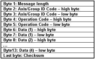
The message length byte contains the total number of bytes of the message minus 2. Put in other words, the length byte value is the number of bytes of the: Axis/group ID Code (2bytes), the Operation Code (2 bytes) and the Data words (variable from 0 to 8 bytes). The Checksum byte is the sum modulo 256 of all the bytes of the message except the checksum byte itself.
Message types on serial communication
The serial communication protocol is based on 3 types of messages imposed by the nature of the TML commands encapsulated:
| • | Type A: Messages that don’t require an answer (a return message). These messages can be sent either by a host or by another drive/motor and contain TML instructions performing parameter settings, motion programming, motor commands, etc. |
| • | Type B: Messages that require an answer. These messages are sent by a host and contain one of the on line TML commands. These commands ask to return data, for example the value of a TML parameter, register, or variable. |
| • | Type C: Messages sent by a drive/motor to a host without being requested by the host. These messages may be sent either when a specific condition occurs or following the execution of the TML command SEND (see Messages sent to the host for details) |
The next paragraphs present an example of each message type.
Example 1 – Type A Message: A host is connected to a drive/motor via RS-232 and sends the TML instruction “KPP = 5” (set proportional part of the position controller with value 5). The axis ID of host and of the drive/motor are 255 = 0FFh. The Axis ID code and the TML instruction binary code are:
Axis ID code + Binary code of TML Instruction KPP = 5 sent to axis 255
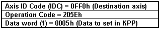
Remark: Use Binary Code Viewer to get the binary code of TML instructions
The host must send a serial message with the following contents:
Serial message: TML Instruction KPP = 5 sent to axis 255
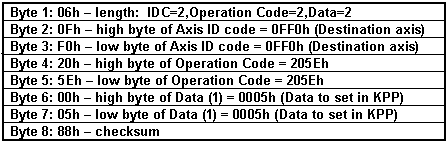
The drive/motor will return a byte 0x4F as confirmation that the message was received OK. (See below the RS-232 and RS-485 protocols description for details)
Remarks:
| a) | If another drive with axis ID=1 is connected via CAN-bus with the drive having axis ID=255 and the host wants to sent the same TML instruction “KPP = 5” to axis 1, the Axis ID Code becomes 0010h instead of 0FF0h. |
| b) | If the host is connected via RS-485 with a drive, the 2 devices must have different axis ID values. For example if the host axis ID = 255 and the drive ID = 1, the message is the same as in remark a) |
Example 2 – Type B Message: A host is connected to a drive via RS-232 and wants to get the value of the KPP (proportional term of the position controller) parameter from the drive. KPP address in TML data memory is 025Eh. The ID of the host and the drive/motor are 255 = 0FFh. The host sends a “GiveMeData” request and the drive/motor answers with a “TakeData” message. Let’s suppose that the KPP value returned by the drive/motor is 288 (120h).
Remark: Use Command Interpreter to get TML data addresses.
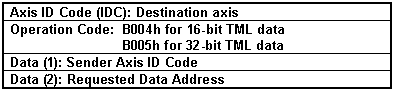
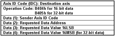
A “GiveMeData” request message for a TML data includes the following information:
“GiveMeData” request for a TML data – Message description
The “TakeData” answer message includes the following information:
“TakeData” answer - Message description
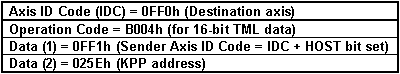
In the particular case of this example, the axis ID code and the binary code of “GiveMeData” are:
Axis ID code + Binary code of “GiveMeData” request for KPP value sent to axis 255
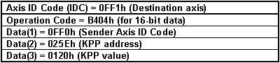
The axis ID code and the binary code of ”TakeData” are:
Axis ID Code + Binary code of “TakeData” with KPP value from axis 255
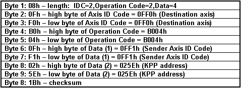
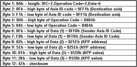
The host must send a “GiveMeData” request message with the following contents:
Serial message: “GiveMeData” request for KPP value sent to axis 255
The drive/motor will return a byte 0x4F as confirmation that the message was received OK (See below the RS-232 and RS-485 protocols description for details), then the “TakeData” answer message with the following contents:
Serial message: “TakeData” with KPP value from axis 255
Remarks:
| a) | If another drive with axis ID=1 is connected via CAN-bus with the drive having axis ID=255 and the host wants to get KPP value from axis 1, the Axis ID Code becomes 0010h instead of 0FF0h in the “GiveMeData” message. The “Take Data” message also will have 0010h in instead of 0FF0h as Sender Axis ID Code. |
| b) | If the host is connected via RS-485 with a drive, the 2 devices must have different axis ID values. For example if the host has axis ID = 255 and the drive has axis ID = 1, the modifications compared with the above examples are: |
| · | “GiveMeData”: Axis ID Code – 0010h instead of 0FF0h and Sender Axis ID Code – 0FF0 instead of 0FF1h (Host bit = 0); |
| · | “TakeData”: Axis ID Code – 0FF0h instead of 0FF1h (Host bit = 0) and Sender Axis ID Code – 0010h instead of 0FF0h; |
Example 3 – Type C Message: A host is connected to a drive via RS-232 and wants to be informed when the programmed motion is completed. The axis ID of the host and the drive/motor are 255 = 0FFh. A Type C message is a “TakeData2” message sent without a “GiveMeData2” request. It includes the following information:
“TakeData2” - Message description
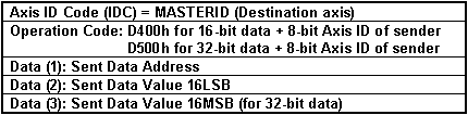
The destination axis is provided by the TML variable MASTERID, according with formula: MASTERID = host axis ID * 16 + 1. In this example, the 8-bit host axis ID = 255, hence MASTERID = 16 * 255 + 1 = 4081 (0xFF1). In the case of a Type C message, the “TakeData2” can return:
| • | The 32-bit value of the 2 status registers SRL (bits 15-0) and SRH (bits 31-16), if one of their selected bits changes (the requested data address is the SRL address) |
| • | The 16-bit value of the error register MER, if one of its selected bits changes |
| • | The 16-bit value of the PVT/PT status PVTSTS, if PVT/PT buffer status changes |
| • | The 16-bit or 32-bit TML data requested to be sent with the TML command SEND. |
Remark: Use Command Interpreter to get the addresses for the above TML data. Note that the SRL and SRH status registers may also be accessed as a single 32-bit variable named SR32.
The bit selection is done via 3 masks, one for each register, set in TML parameters: SRL_MASK, SRH_MASK, MER_MASK. A bit set in a mask, enables a message transmission when the same bit from the corresponding register changes. In this example, the motion complete condition is signaled by setting SRL.10 = 1. To activate automatic sending of a “TakeData2” whenever SRL.10 changes, set SRL_MASK = 0x0400.
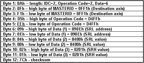
If SRH = 0x201 and SRL = 0x8400, after SRL.10 goes from 0 to 1, the host gets a “TakeData2” message with the following contents:
Serial message: “TakeData2” with status registers SRL and SRH from axis 255
Remark: A “TakeData2” message with SRL.10=1 signals that the last programmed motion is completed. A “TakeData2” message with SRL.10=0 signals that a new motion has started and may be used as a confirmation for the last motion command.
RS-232 communication protocol
The RS-232 protocol is full duplex, allowing simultaneous transmission in both directions. After each command (Type A or B) sent by the host, the drive will confirm the reception by sending one acknowledge-Ok byte. This byte is: ‘O’ (ASCII code of capital letter “o”, 0x4F). If the host receives the ‘O’ byte, this means that the drive has received correctly (checksum verification was passed) the last message sent, and now is ready to receive the next message.
Remark: If the destination axis for the message is not the axis connected with the host via RS-232 (e.g. the relay axis), but another axis connected with the relay axis via CAN-bus, the reception of the acknowledge-Ok byte from the relay axis doesn’t mean that the message was received by the destination axis, but just by the relay axis. Depending on the CAN-bus baud rate and the amount of traffic on this bus, the host may need to consider introducing a delay before sending the next message to an axis connected on the CAN-bus. This delay must provide the relay axis the time necessary to retransmit the message via CAN-bus.
If any error occurs during the message reception, for example the checksum computed by the drive axis doesn’t match with the one sent by the host, the drive will not send the acknowledge-Ok byte. If the host doesn’t receive any acknowledge byte for at least 2ms after the end of the checksum byte transmission, this means that at some point during the last message transmission, one byte was lost and the synchronization between the host and the relay axis is gone. In order to restore the synchronization the host should do the following:
| 1) | Send a SYNC byte having value 0x0d (higher values are also accepted) |
| 2) | Wait a programmed timeout (typically 2ms) period for an answer; |
| 3) | If the drive sends back a SYNC byte having value 0x0d, the synchronization is restored and the host can send again the last message, else go to step 1 |
| 4) | Repeat steps 1 to 3 until the drive answers with a SYNC byte or until 15 SYNC bytes are sent. If after 15 SYNC bytes the drive/motor still doesn’t answer, then there is a serious communication problem and the serial link must be checked |
When a host sends a type A message through RS-232 it has to:
| a) | Send the message (as in Example 1); |
| b) | Wait the acknowledge-OK byte ‘O’ from the drive; |
When a host sends a type B message through RS-232 it has to:
| a) | Send the request message (as in Example 2 in case of a “Give Me Data” command) |
| b) | Wait the acknowledge-OK byte ‘O’ from the drive connected via RS-232 (relay axis); |
| c) | Wait the answer message from the drive/motor (as in Example 2, in case of a “Take Data” answer) |
When the relay axis returns an answer message it doesn’t expect to receive an acknowledge byte from the host. It is the host task to monitor the communication. If the host gets the response message with a wrong checksum, it is the host duty to send again the data request.
RS-485 communication protocol
The RS-485 protocol is half duplex. If two devices start by mistake to transmit in the same time, both transmissions are corrupted. Therefore for a correct operation, in an RS-485 network it is mandatory to have a master, which controls the transmission. This means that only the master can initiate a transmission, while all the other devices from the network may transmit only when the master asks them to provide some data. Usually you should set as master your host.
After each command (Type A or B) sent by the host to one drive, the drive will confirm the reception by sending one acknowledge-Ok byte. This byte is: ‘O’ (ASCII code of capital letter “o”, 0x4F). If the host receives the ‘O’ byte, this means that the drive has received correctly (checksum verification was passed) the last message sent, and now is ready to receive the next message.
The acknowledge-Ok byte is not sent when the host broadcasts a message to a group of drives.
If any error occurs during the message reception, for example if the checksum computed by the drive axis doesn’t match with the one sent by the host, the drive will not send the acknowledge-Ok byte. If the host doesn’t receive any acknowledge byte for at least 2ms after the end of the checksum byte transmission, this means that at some point during the last message transmission, one byte was lost and the synchronization between the host and the relay axis is gone. In order to restore the synchronization the host should do the following:
| 1) | Send 15 SYNC bytes having value 0x0d or any other bigger value up to 0xFF |
| 2) | Wait a programmed timeout (typically 2ms); |
| 3) | Send again the last command and wait for the drive answer |
| 4) | If the drive still doesn’t answer, then there is a serious communication problem and the serial link must be checked |
When a host sends a type A message through RS-485 it has to:
| a) | Send the message (as in Example 1); |
| b) | Wait the acknowledge-OK byte ‘O’ from the drive, only if the message destination was a single drive; |
When a host sends a type B message through RS-485 it has to:
| a) | Send the request message (as in Example 2 in case of a “Give Me Data” command) |
| b) | Wait the acknowledge-OK byte ‘O’ from the drive; |
| c) | Wait the answer message from the drive/motor (as in Example 2, in case of a “Take Data” answer) |
Remarks:
| • | When using the RS-485 protocol, do not send Type B request messages to a group of axes, because the answer messages will overlap |
| • | When using the RS-485 protocol, the Type C messages must be suppressed. Only the host/master is allowed to initiate a transmission |
When a drive returns an answer message it doesn’t expect to receive an acknowledge byte from the host. It is the host task to monitor the communication. If the host gets the response message with a wrong checksum, it is the host duty to send again the data request.
See also:
Communication protocols – Overview
CAN-bus communication. TMLCAN protocol