The data exchange on any communication bus and protocol is done using messages. Each message contains one TML instruction to be executed by the receiver of the message. Apart from the binary code of the TML instruction attached, any message includes information about its destination: an axis (drive/motor) or group of axes. This information is grouped in the Axis/Group ID Code. Depending on the communication bus and the protocol used, the Axis/Group ID Code and the binary code of the TML instruction attached are encapsulated in different ways.
Information included in a communication message
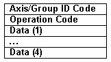
The first word Axis/Group ID Code identifies the destination axis or the group of axes that must receive the message. The next words represent the codification of the TML instruction transmitted.
The Axis/Group ID Code is a 16-bit word with the following structure:
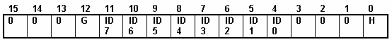
Where:
Bit 0 – HOST bit. 0 – relay axis, 1 – host. When a host is connected with a drive using RS-232, the 2 devices must have the same axis ID (bits ID7-ID0 are identical). The HOST bit makes the difference between the host and the drive connected to the other end. On RS-485, the host and the drives have different axis ID, the HOST bit has as no significance and must be set to 0.
Bits 11-4 – ID7-ID0: the 8-bit value of an axis ID or group ID
Bit 12 – GROUP bit: 0 – ID7-ID0 value is an axis ID, 1 – ID7-ID0 value is a group ID
Depending on the communication bus and protocol used, either the entire 16-bit Axis/Group ID code is included in a message or only a part of it. This part can be the 10 bits with useful information: HOST bit, ID7 – ID0 bits and the GROUP bit or a subset of those.
Remark: In the following paragraphs, the terminology Axis ID Code or Group ID Code designates the above 16-bit word. The terminology Axis ID and Group ID designates the 8-bit value of an axis or group ID i.e. value of bits ID7 – ID0.
The following example describes how the HOST bit is used: Let’s suppose that we have 2 drives with the axis ID=1 and axis ID=2 (values 1 and 2 represent the value of the bits ID7-ID0) connected between them via CAN-bus. The host is connected via RS-232 to the drive with axis ID=1 which acts as a relay axis. The host axis ID (host ID) must also be 1 but with the HOST bit set. The host sends a data request message to the drive with the axis ID=2. The axis ID code of this request message is 2 e.g. the destination axis. The message includes the sender axis ID code e.g. where the drive with ID=2 must send the data requested. The sender axis ID code is the host address (ID=1 and the HOST bit set). The request message is sent via RS-232 to drive with axis ID=1. This drive observes that the message destination is another axis (e.g. ID=2) and resends the message via CAN-bus. The drive with the axis ID=2, will receive the request message and send the answer via CAN-bus to the sender axis (e.g. host). As the host has the same address as the relay axis, all the messages sent via CAN-bus and having as destination the host are received by the relay axis. The relay axis looks at the HOST bit: if the bit is set, then the message received is sent back via RS-232 to the host. If the HOST bit is not set, then the message received is executed (it’s destination is the relay axis).
A message can be sent to an axis or to a group of axes. In the first case, the destination is specified via an Axis ID code. In the second case, the destination is specified via a Group ID code. Each drive/motor has its own 8-bit Axis ID and Group ID stored in the AAR TML register. If the destination of a message is specified via an Axis ID code, the message is received only by the axis with the same 8-bit Axis ID (bits 11-4 from the 16-bit Axis ID code). If the destination of a message is specified via a Group ID code, each axis compares the 8-bit group ID from the message with its own group ID. If the two group IDs have at least one group (bit set to 1) in common, the message is accepted. In the group ID, each bit corresponds to one group:
Definition of the groups
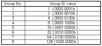
A drive/motor can be programmed to be member of up to 8 groups. It will accept all the messages sent to any of the groups his is member. For example, if the drive is member of groups 1, 2 and 4, i.e. its 8-bit Group ID = 11 (00001011b), it will receive all the messages which have in their group ID value at least one of the bits 0,1 or 3 set to 1.
Remarks:
| • | A message with axis ID = 0 and will be accepted independently of the receiver axis ID |
| • | A broadcast message has the group ID = 0 and will be accepted by all the axes from the network, independently of their group ID |
On each drive/motor, the axis ID is initially set at power on using the following algorithm:
| a. | With the value read from the EEPROM setup table containing all the setup data. |
| b. | If the setup table is invalid, with the last axis ID value read from a valid setup table |
| c. | If there is no axis ID set by a valid setup table, with the value read from the hardware switches/jumpers for axis ID setting |
| d. | If the drive/motor has no hardware switches/jumpers for axis ID setting, with the default axis ID value which is 255. |
Remark: If the axis ID read from a valid setup table is 0 (option H/W), the axis ID is set with the value read from the hardware switches/jumpers or in their absence with the default value 255
On each drive/motor, at power on, the group ID is set to 1 i.e. all drives/motors are members of the group 1. For each drive/motor you can:
| • | Set/change its group ID using the TML instruction GROUPID |
| • | Add new groups to its group ID using the TML instruction ADDGRID |
| • | Remove groups from its group ID using the TML instruction REMGRID. |
Remark: You can read at any moment the actual values of the axis ID and group ID of a drive/motor from the Axis Address Register AAR
The TML instruction code can have 1 to 5 words. All the TML instructions have at least one word – the Operation Code. Depending on the type of TML instruction, the operation code may be followed by 0-4 Data words.
Remark: Use Binary Code Viewer to get the binary code of TML instructions
See also:
Communication protocols – Overview
Serial communication. RS-232 and RS-485 protocols
CAN-bus communication. TMLCAN protocol
CAN-bus communication. TechnoCAN protocol