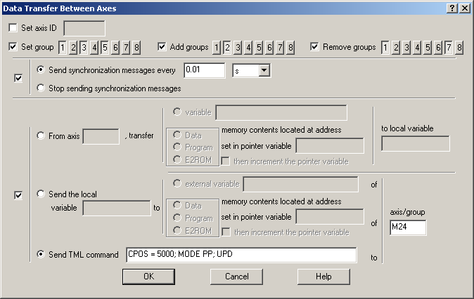
The “Data Transfer Between Axes” dialog allows you to program data transfer operations between drives/motors connected in a network. From this dialog, you can also change the axis ID – the drive/motor network address, and the groups it belongs for multicast transmissions as well as to activate/deactivate the synchronization between axes.
Check Set axis ID if you want to change the axis ID and set a new value. The axis ID is a value between 1 and 255. It is initially set at power on using the following algorithm:
| a. | With the value read from the EEPROM setup table containing all the setup data. If this value is 0, the axis ID is set with the value read from the hardware switches/jumpers or in their absence according with d) |
| b. | If the setup table is invalid, with the last axis ID value read from a valid setup table |
| c. | If there is no axis ID set by a valid setup table, with the value read from the hardware switches/jumpers for axis ID setting |
| d. | If the drive/motor has no hardware switches/jumpers for axis ID setting, with the default axis ID value which is 255. |
Remark: Typically, the axis ID is kept constant during operation at the value established during the setup phase. However, if needed, you can change the axis ID to any of the 255 possible values, using the above command
In EasyMotion Studio, each application has associated an Axis Number, set in Application General Information. When an application is selected, all the data exchange operations are performed with the drive/motor having the same axis ID as the application Axis Number. An axis ID change may create communication problems, if this is performed during operation i.e. if the drive/motor starts with one axis ID and later on switches to another axis ID.
Check Set group if you want set the groups to which a drive/motor belongs. A group is way to identify a number of drives, for a multicast transmission. Each drive can be programmed to be member of one or several of the 8 possible groups (up to all). A drive will accept all the messages sent to any of the groups it belongs. Push the buttons for the groups the drive/motor will belong. Use Add groups or Remove groups to add or remove your drive/motor from one or several groups.
Remark: A message can be:
| • | Sent to an axis defined by an Axis ID |
| • | Multicast to one group of axes defined by a Group ID. The Group ID is an 8-bit value, where each bit set represents a group. For example, a multicast to Group ID = 4 (100b) will be received by all drives from group 3. |
| • | Broadcast to all nodes, if the Group ID = 0. |
Check Synchronization group to activate/deactivate the synchronization procedure. This procedure requires activating one axis as a synchronization master. The other axes are deactivated and are synchronization slaves. Select Send synchronization messages every… and set the time interval between synchronization messages, to activate the synchronization master. Recommended starting value for the time interval is 20ms. When synchronization procedure is active, the execution of the control loops on the slaves is synchronized with those of the master within a 10µs time interval. Due to this powerful feature, drifts between master and slave axes are eliminated. Deactivate the synchronization procedure by choosing Stop sending synchronization messages. This will disable the synchronization master and set the axis as a synchronization slave. In the absence of a master, the synchronization process is stopped.
The data transfer operations may be split into three categories:
| 1. | Read data from a remote axis. A variable or a memory location from the remote axis is saved into a local variable |
| 2. | Write data to a remote axis or group of axes. A variable or a memory location of a remote axis or group of axes is written with the value of a local variable |
| 3. | Send TML commands from local drive to a remote drive or group of drives |
Check data transfer commands, and select From axis to read from the remote axis specified, the value of a variable or the data / program / E2ROM memory contents located at an address set in a pointer variable. The data is saved in the local TML variable indicated in to local variable field. The local variable can be either a 16-bit or a 32-bit TML data. Its type, dictates the data transfer size. Check then increment the pointer variable to automatically increment the pointer by one or two function of the local variable type, after the transfer is performed. The memory type is split into 3 categories: data – for the RAM area for TML data, program – for the RAM area for TML programs and E2ROM – for the EEPROM area for TML programs.
Select Send the local variable to copy on a remote axis or group of axes, the value of the local variable specified. The data is saved either in an external/remote variable or in the data / program / E2ROM memory location(s) from address set in the pointer variable indicated. The local variable can be either a 16-bit or a 32-bit TML data. Its type, dictates the data transfer size. Check then increment the pointer variable to automatically increment the pointer by one or two function of the local variable type, after the transfer is performed. The memory type is split into 3 categories: data – for the RAM area for TML data, program – for the RAM area for TML programs and E2ROM – for the EEPROM area for TML programs. The destination specified at axis/group can be:
| • | An axis ID set with a number between 1 and 255 |
| • | A group set with letter G followed by a number between 1 and 8. Examples: G1, G7 |
| • | A broadcast to all axes set with letter B |
Select Send TML command to program the local axis to transmit the TML command(s) you type in the associated field towards the destination specified in the axis/group field. The transmission is done when the command is executed.
Remarks:
| • | This command offers a very powerful tool through which one drive/motor may control other drives/motors from the network. For example it can start or stop the other drives motion or check their status |
| • | You may type multiple TML commands separated by semicolon (;). These will be sent one by one in the order of occurrence in the edit. |
| • | Via this type of messages, you can send all the TML instructions having an instruction code of maximum 4 words. In this category enter most of the TML commands (see TML Instruction Coding and the detailed description of the TML Instructions). |
OK: Close this dialogue and save the operations selected in your motion sequence list.
Cancel: Close this dialogue without saving anything in your motion sequence list.
Help: Open this help page.
See also: