This application note describes the available start modes. The start modes are special procedures required to align the magnetic fields in the motor.
Start modes description
The preferred start mode can be selected during the setup phase, trough the “Drive Setup” dialogue.
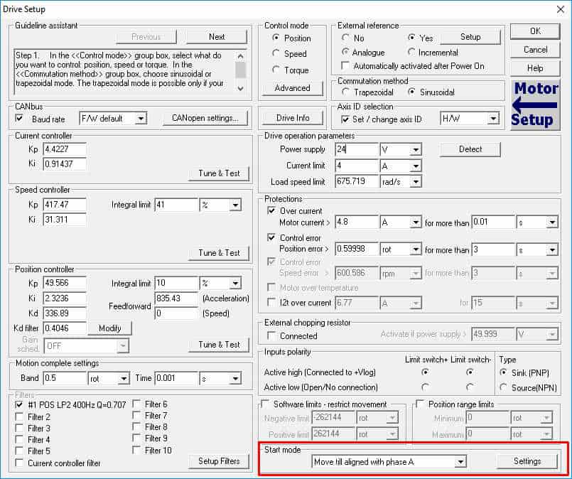
Figure 1. Start mode selection
Depending on the system configuration (drive model, motor type and feedback sensors) the available start modes varies from a project to another. A complete list with the available start modes is presented below.
1) Move till aligned with phase A;
2) BLDC with Hall sensors;
3) PMSM with Hall sensors;
4) Direct start, using the absolute position sensor;
5) Motionless start (encoder only).
The start mode selection will be done function on the application requirements and on the system configuration. For example, in case of a gravitational system (vertical axis) that is not equipped with an absolute position sensor, the recommended start modes are “BLDC / PMSM with Hall sensors” (if the motor is equipped with digital Hall sensors) or to “Motionless start (encoder only)”.
The “Move till aligned with phase A” start method is not recommend because the load might be in a mechanical limit and this will not allow the motor to perform the needed alignment movements.
1.1. “Move till aligned with phase A” start mode
This start method assume a small motor movement that has the purpose to align the magnetic field from rotor with phase “A” of motor. For this, the motor is energized to align first with phase B, then with phase A. This has the purpose to avoid the situation when the initial electrical angle between the magnetic field from the rotor and the phase “A” of the motor is 180 degrees.
Remark: If the electrical angle between the magnetic field from the rotor and the phase “A” of the motor is 180 degrees, then the rotor will not move if the phase “A” of the motor is energized. That is why this
start mode energizes first the phase “B” of the motor. When the “Move till aligned with phase A” start mode is selected, the “Settings” button will appear in the “Start mode” section.
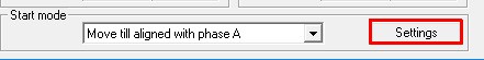 Figure 2. “Move till aligned with phase A” start mode settings button
Clicking on this button the following dialog will open.
 Figure 3. “Move till aligned with phase A” start mode settings
This dialog allows setting the current that will be used during the alignment procedure (as percentages from the motor nominal current, defined in the “Motor Setup” dialog) and the “time to apply on phase”.
The used current value depends on the mechanical system inertia. To avoid a start method failing the used current value can be set to 90% or 100% from the motor nominal current.
Remark: If the mechanical system has sticktion or a very high inertia, the alignment current can be also set to 110% or 120% from the motor nominal current.
The “Move till aligned with phase A – Settings” dialog allows also to enable/disable a protection that detects if the start mode failed. If the respective parameter is set to 0 %, the protection is disabled. Any other value will activate the protection and set its level to the respective value. For example, 70% means that the protection is active and set to 70% from the expected movement (70% from 120 electrical degrees).
 Figure 4. “Move till aligned with phase A” start mode protection setting
This start method can be used for all applications with horizontal loads, using motors without Hall sensors and where the motor can move freely.
1.2. “BLDC and PMSM with Hall sensors” start modes
These start modes are available only in case of motors equipped with digital Hall sensors.
Compared with the “Move till aligned with phase A” start mode, the start methods based on the digital Hall sensors have the advantage that does not involve an initial movement of the motor. The command is adjusted based on the first read Hall combination.
In order for this start modes to work correctly, is very important to detect the Hall configuration. This can be done during the setup phase through the “Motor Setup” dialog.
 Figure 5. Detect the digital Hall sensors configuration
The “BLDC with Hall sensors” method starts the motor using the trapezoidal commutation method and commutes to sinusoidal after the first Hall sensors transition is detected.
The “PMSM with Hall sensors” method starts the motor directly in the sinusoidal mode and adjusts the electrical angle after the first transition of the Hall sensors. Due to this, it is smoother than the “BLDC with Hall sensors” method. These start modes are recommended for applications where an uncontrolled movement of the motor is not allowed or where mechanical limits might be involved.
1.3. “Direct start using the absolute position sensor” method
To control the motor using a FOC method, the drive needs to know the rotor position. In case of the absolute position sensors, the rotor position is always known, so the drive can start the motor directly. If this start mode is selected, a mandatory step is to detect the absolute sensor offset. This test is available in the “Motor Setup” dialog and has the purpose to check the absolute sensor indication, when the rotor is aligned with the phase “A” of the motor.
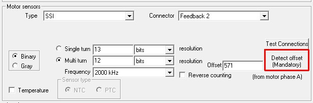
Figure 6. Absolute position sensor offset detection
1.4. “Motionless start (encoder only)” method
In absence of an absolute position sensor / digital Hall sensors, the drive needs to align the motor with a known position. This alignment is mandatory for an optimal vector control, where the internal angle of the motor is kept at 90 degrees, to ensure maximal torque generation with minimum current consumption.
This alignment is usually done using the “Move till aligned with phase A” start mode but as was explained above, there are some cases where this start method cannot be used.
The “Motionless start” method was developed to alleviate this drawback.
To do the initial alignment, the “Motionless start” method uses an angle controller and the notions of “stator” and “rotor” are reversed. Instead of physically moving the rotor, to align it with the stator, the drive moves the electromagnetic field, generated on the stator to “find” the actual position of the rotor. For that, a small movement is still needed but compared to the maximum travel of 240 electrical degrees, in case of the “Move till aligned with phase A” start mode, here the movement has only few electrical degrees.
To avoid rotor movement the information from the encoder is read and to react automatically on the rotor position change an angle controller is used. The angle controller is PI type and can be accessed from the “Drive Setup” dialog.
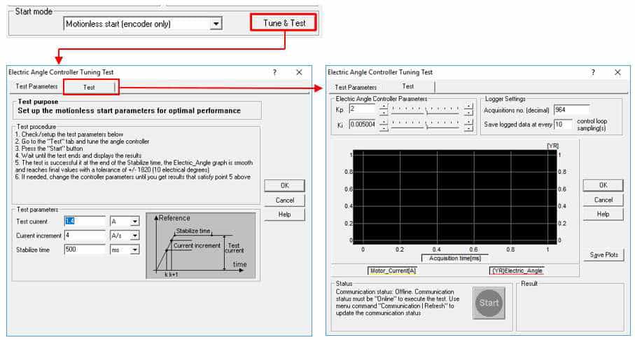
Figure 7. Angle controller tuning
The “Motionless start” method is slightly more complex in setup than any of the other available methods and sometimes it may require a manual tuning.
