This application note describes how to implement a homing routine, using a function that aligns the load to the middle of the working area.
The homing procedure follows the algorithm below:
- move negative until the negative limit switch is reached;
- stop and set the current position to 0 [IU];
- move positive until the positive limit switch is reached;
- move to the middle of the working area;
- set this position as the system home position.
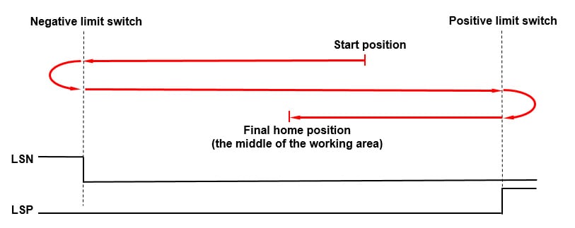
Figure 1. Homing steps
Application flow chart
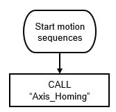
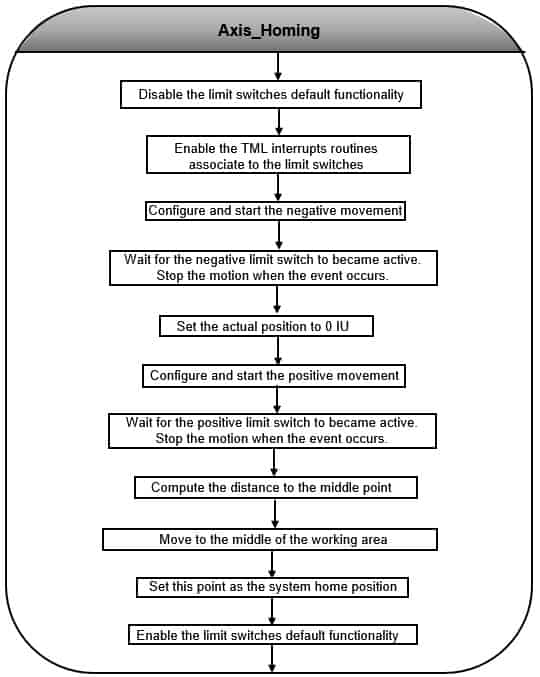
Figure 2. Application structure
EasyMotion Studio implementation

Figure 3. Main section of the TML program
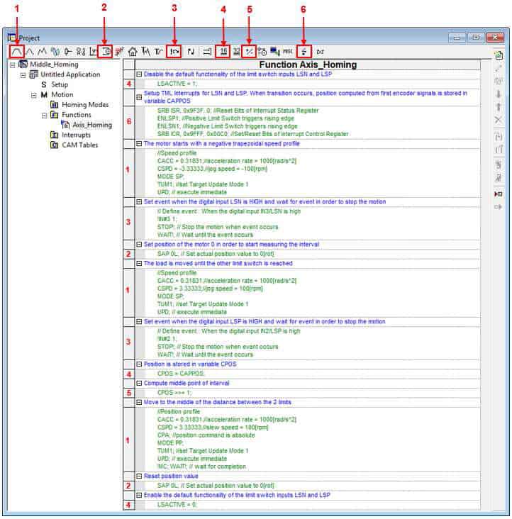
Figure 4. Function Edit
Detailed description of the EasyMotion Studio implementation
1.1.Motion section
The “Jumps and Function Calls” dialogue allows controlling the TML program flow through unconditional or conditional jumps and unconditional, conditional or cancelable calls of TML functions.
In this case, it was used to call the “Axis_Homing” function.
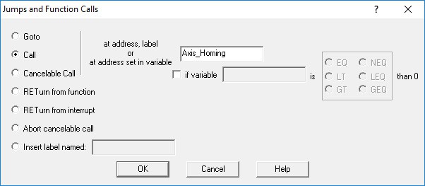
Figure 5. How to call a TML function
1.2. Functions section
The “Functions” section allows creating, renaming or removing a function. In this case, it was used to create the “Axis_Homing” function that contains the functionality described in the first chapter.
Once a TML function is created, it will appear in the “Functions” section.
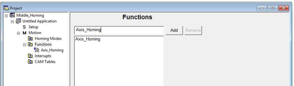
Figure 6. How to create a TML function
The code inside the “Axis_Homing” function was generated using the buttons marked with 1 to 6 in Figure 4. Clicking on those buttons, the following programming dialogues will open.
The “Assignment and Data Transfer – 16 bit Integer Data” dialogue (4) allows different operations with the 16-bit integer variables / parameters / registers. Here it was used to set the LSACTIVE parameter value to 1. This is deactivating the default functionality of the hardware limit switches. For more details please check the” Drive special inputs – Limit Switches” application note.

Figure 7. How to disable the default functionality of the limit switch inputs
The “Interrupt Settings” dialogue (6) allows to activate and/or deactivate the TML (Technosoft Motion Language) interrupts. In this case, it was used to activate “int 6- LSP programmed transition detected” and “int 7- LSN programmed transition detected” interrupts routines.
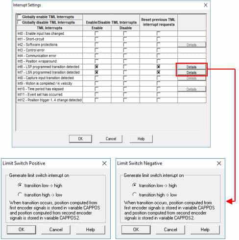
Figure 8. Interrupt Settings dialogue
Remark: The limit switches interrupts were enabled to activate the position capture when the limit switches became active.
The “Motion – Trapezoidal Profiles” dialogue (1) allows to program a position or speed profile. It was used to move the motor in the negative direction, as the first part of the homing procedure requires (move negative until the negative limit switch became active).

Figure 9. How to set a negative motion profile
By default, when a limit switch became active, the drive stops the movement using a quick stop profile. In this case, the default functionality of the limit switches was deactivated, so a stopping mechanism is required, when the negative limit switch is reached, due to the above motion profile.
The stopping mechanism mentioned above, was implemented using the “Events” dialogue (3), that was set to wait until the negative limit switch became active and then, to stop the motor.

Figure 10. Setting an event on the IN(3)/LSN digital input
Once the negative limit switch is reached, the motion stops and the actual position is set to 0, using the “Motion – Motor Commands” dialogue (2).
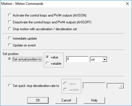
Figure 11. How to set position value
The “Motion – Trapezoidal Profiles” dialogue (1) is used again, to reverse the motor and go positively until the positive limit switch is reached.

Figure 12. How to set a positive motion profile
The positive limit switch detection is done using the “Events” dialogue (3). This time it is set to wait until the positive limit switch became active and then to stop the motion.

Figure 13. Setting an event on the IN(2)/LSP digital input
The “Assignment and Data Transfer – 16 bit Integer Data” dialogue (4) is used to set the command position with the captured position (when the positive limit switch was reached).
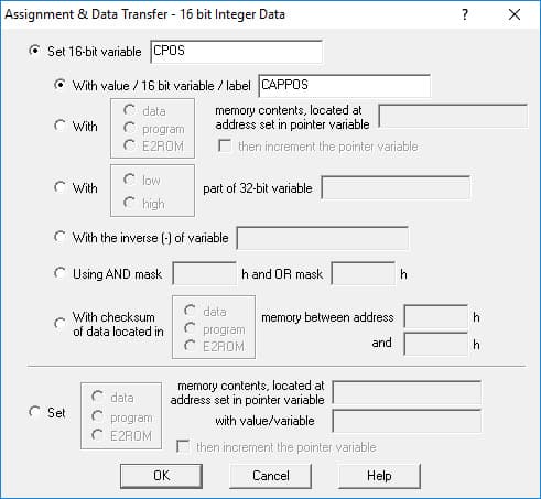
Figure 14. Position stored in variable CPOS
Remark: If the limit switches interrupts are active, then each time one of the limits is reached the drive saves automatically the actual position in the CAPPOS internal variable.
Since the position was set to 0 IU when the negative limit switch was reached, the position captured now represents the exact distance (in encoder counts) between the two limit switches. So, the middle point can be computed by dividing this value to 2.
At the processor level, the division is done through repetitive subtractions. Since the captured position needs to be divided to half, the shifting operations can be also used. The shift to the right, with 1 bit is equivalent with the division with 2^1 and it is also executed faster than the division. That is why the shifting operation is used instead the division.
The shifting operations are available in the “Arithmetic Operations” dialog (5).
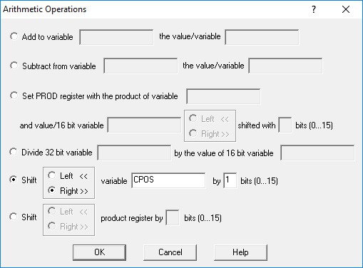
Figure 15. Compute the distance to the middle point
Once the middle point coordinate is computed, the load is moved there using the “Motion – Trapezoidal Profiles” dialogue (1).
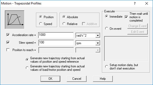
Figure 16. Position Profile
Remark: The profile above is absolute, because the value computed above represents the position to reach (the absolute position) not the position increment.
After the load reaches the middle of the working area, the respective position is set to 0 and represents the system homing point. This operation was done using the “Motion – Motor Commands” dialogue (2).
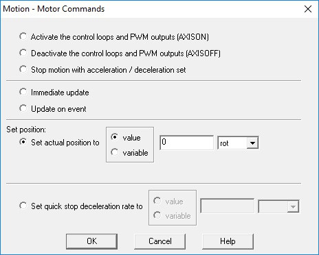
Figure 17. Reset position value
Before returning from function, the “Assignment and Data Transfer – 16 bit Integer Data” dialogue (4) is used to restore the limit switches default functionality by setting the LSACTIVE variable value to 0 (for reference, see Figure 7).