The “Motion – Electronic Camming” dialogue allows you to set a drive/motor as master or slave for electronic camming mode.
When set as master, a drive/motor sends its position via a multi-axis communication channel, like the CAN bus. The master sends either the load position or the position reference once at each slow loop sampling time interval.
When set as slave, a drive/motor executes a cam profile function of the master position. The cam profile is defined by a cam table – a set of (X, Y) points, where X is cam table input i.e. the master position and Y is the cam table output i.e. the corresponding slave position. Between the points the drive/motor performs a linear interpolation. Using Cam Tables Selection selection you can associate cam tables to your application. These may be visualized and modified using the Cam Tables Edit. You may also import cam tables. The required format is: text file with 2 columns, one for X, and the other for Y, separated by space or tab. Data must be in internal units.
The slaves can get the master position in two ways:
| 1. | Via a communication channel, from a drive/motor set as master |
| 2. | Via an external digital reference of type pulse & direction or quadrature encoder. Both options have dedicated inputs. The pulse & direction signals are usually provided by an indexer and must be connected to the pulse & direction inputs of the drive/motor. The quadrature encoder signals are usually provided by an encoder on the master and must be connected to the 2nd encoder inputs. |
Remark: For 2nd option you don’t need to program a drive/motor as master in electronic camming
Select Master tab to set a drive/motor as master in electronic camming.
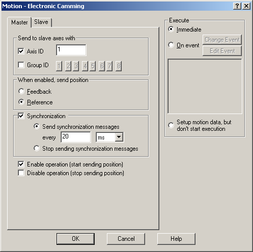
If the master sends its position to a single drive/motor, check the Axis ID and fill the associated field with the axis ID of the slave. If the master sends its position to more drives, indicate the Group ID of the slaves. Select one group of drives (1 to 8) to which the master should send its position.
Remark: You need to specify the Axis ID or the Group ID where master sends its position only the first time (after power on) when a drive is set as master. If the master mode is later on disabled, then enabled again, there is no need to set again the Axis ID or the Group ID, as long as they remain unchanged. In this case, just uncheck both the Axis ID and the Group ID.
Select Feedback, to set the master sending its load position, or Reference, for sending its position reference.
Remark: The feedback option is disabled if the master operates in open loop. It is meaningless if the master drive has no position sensor.
Check Synchronization to activate the synchronization procedure between the master and the slave axes. Select Send synchronization messages and set the time interval between synchronization messages. Recommended starting value is 20ms. When synchronization procedure is active, the execution of the control loops on the slaves is synchronized with those of the master within a 10µs time interval. Due to this powerful feature, drifts between master and slave axes are eliminated. Select Don’t send synchronization to disable the synchronization procedure.
Check Enable operation to activate the master mode and start the sending of master position to the slaves. Check Disable operation to deactivate the master mode and stop sending of master position to the slaves. Note that enabling or disabling master operation has no effect on the motion executed by the master.
Choose Execute Immediate to enable the slave operation mode immediately when the motion sequence is encountered. Choose Execute On Event to start the slave operation mode when a programmable event occurs. Click Change Event to select the event type or Edit Event to modify the parameters of the selected event (see Events for details). Select Setup motion data, but don’t start execution if you want to prepare the slave operation mode for a later execution.
Select Slave tab to set a drive/motor as slave in electronic camming.

Select the camming mode:
| • | In Relative mode, the output of the cam table represents for the slave a position increment, which is added to its actual position |
| • | In Absolute mode, the output of the cam table represents for the slave the position to reach. |
Remark: The absolute mode may generate abrupt variations on the slave position reference, mainly at entry in the camming mode. Check Limit maximum speed at to limit the speed of the slave during travel towards the position to reach.
Check Use CAM table and choose between the selected cam tables which one to use.
Remark: Note that at runtime, all the selected cam tables are loaded into the drive memory. If needed, you may switch between the cam tables loaded. This operation means just to change the value of the CAMSTART parameter which points towards the active cam table.
Check Offset from master in IU to shift the cam profile versus the master position, by setting a cam offset for each slave. The cam table input is computed as the master position minus the cam offset. For example, if a cam table is defined between angles 100 to 250 degrees, a cam offset of 50 degrees will make the cam table to execute between master angles 150 and 300 degrees.
Check Multiply table input with to compress/extend a cam table input. Specify the input correction factor by which the cam table input is multiplied. For example, an input correction factor of 2, combined with a cam offset of 180 degrees, will make possible to execute a cam table defined for 360 degrees of the master in the last 180 degrees.
Check Multiply table output with in order to compress/extend a cam table output. Specify the output correction factor by which the cam table output is multiplied. This feature addresses the applications where the slaves must execute different position commands at each master cycle, all having the same profile defined through a cam table. In this case, the drive/motor is programmed with a unique normalized cam profile and the cam table output is multiplied with the relative position command updated at each master cycle.
Check Enable operation with master position and select how to get the master position: via communication or via an external reference. Leave unchecked if you want to set the slave parameters without enabling slave operation mode.
Check Master Resolution to specify the number of encoder counts per one revolution of the master motor. The slaves need the master resolution to compute correctly the master position and speed (i.e. position increment). Select Full range if master position is not cyclic (e.g. the resolution is equal with the whole 32-bit range of position). In this case the master resolution is set to value 0x80000001.
Select Generate new trajectory starting from actual values of position and speed reference if you want the reference generator to compute the slave position starting from the actual values of the position and speed reference. Select Generate new trajectory starting from actual values of load/motor position and speed if you want the reference generator to compute the slave position starting from the actual values of the motor position and speed.
Choose Execute Immediate to enable the slave operation mode immediately when the motion sequence is encountered. Choose Execute On Event to start the slave operation mode when a programmable event occurs. Click Change Event to select the event type or Edit Event to modify the parameters of the selected event (see Events for details). Select Setup motion data, but don’t start execution if you want to prepare the slave operation mode for a later execution.
OK: Close this dialogue and save the motion sequence in your motion sequence list.
Cancel: Close this dialogue without saving the motion sequence in your motion sequence list.
Help: Open this help page
See also:
Electronic Camming – TML Programming details
Electronic Camming –TML Instruction and Data
Internal Units and Scaling Factors