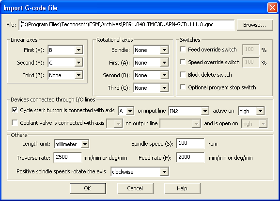
The “Import G-code file” dialogue allows you to convert G-code sequences into TML motion language.
This option is enabled if your project includes a multi-axis Motion Controller.
In the multi-axis Motion Controller application window left side, select “M Motion”, for motion programming. Choose in the “Application/Motion/Import G-code file…” menu option, which will open the “Import G-code file” dialogue.
Use the Browse button to select the G-code file. The file extension shall be .gnc. Just one G-code file could be imported at one time.
For each G-code program imported you can:
Set the specific axes
The dialog allows you to set the linear axes (X, Y, Z), the rotational axes (A, B, C) and the spindle axis. For each selection, you can choose from a drop-down list, one of the axes previously defined in Axis Selection
Remark: For the Spindle axis the list will contain only the rotational axes that have the speed loop closed.
Activate switches
The dialog allows you to set the following switches:
| • | Feed override switch. The default value is 100%. You can modify this value by checking the specific switch and changed the percentage value. By enabling this switch with a value different than 100%, you can limit the feed values to a percentage of the defined value. |
| • | Speed override switch. The default value is 100%. You can modify this value by checking the specific switch and changed the percentage value. By enabling this switch with a value different than 100%, you can limit the speed values to a percentage of the defined value. |
| • | Block delete switch. By default this switch is disabled. If enabled, the lines that start with slash (the block delete character) will not be interpreted. |
| • | Optional program stop switch. By default this switch is disabled, and the stop words are not interpreted. If enabled, the program execution will stop when M1 code is encountered. The program execution will be resumed when the cycle start button is pushed (See below Devices connected though I/O lines). |
Define devices connected though I/O lines
| • | Input for cycle start button. Set the specific axis, the input line and the polarity (when the input line is active). |
Remark: If optional stop switch enable, M1 encounter and no cycle start button defined the program will jump to the beginning of the code.
| • | Output for coolant valve. Set the specific axis, the input line and the polarity (when the output line is active). |
Set various movement parameters:
| • | Length units. You can choose between millimeter and inch. |
| • | Spindle speed (S) and rotational direction. Choose between clockwise or counter clockwise, depending on your mechanical stand. By default the positive sense of rotation is clockwise. |
| • | Traverse rate (T) |
| • | Feed rate (F) |
See also: