How Can We Help?
Speed control of a brushless motor equipped only with digital Hall sensors
When a brushless motor is equipped only with digital Hall effect sensors and the speed control is required, a special control algorithm can be used. This algorithm is included in the last firmware versions for the iPOS drives and requires a special hardware connection: the Hall sensors will be connected to the correspondent drive inputs but 2 of the Hall sensor will also be connected to the “Encoder A+” and “Encoder B+” terminals.
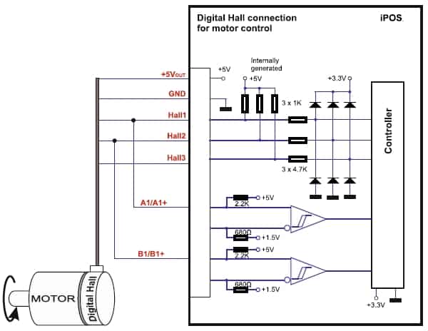
Remarks:
1. Do not connect unterminated wires. They might pick up unwanted noise and give false encoder readings.
2. The length of the cables must be up to 30m, reducing the exposure to voltage surges in industrial environment.
3. The encoder circuit on the respective drive should be set for single ended sensors (no 120 Ohms terminators should be connected between the encode lines).
From software point of view, in case of the 24 V and 36 V drives, the control using the digital Hall sensors is available as separate configuration.
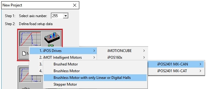
In case of the 48 V and 80 V drives, this option is included in the standard templates for the brushless motors.
From this point forward, the motor and drive setup will be done as in case of any other configuration.
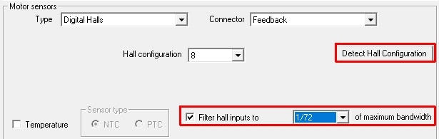
Tips and Tricks for the “digital Hall only” configuration1. Hall signals filtering
When working with the digital Hall sensors as main feedback, there is also an important aspect related to the noises. If the Hall sensors signals have noises, the control will be affected or even be compromised. To reduce / eliminate the noises, the firmware provides some software filters that can be set through the following parameters:
> HIGH_SPD_FILTER
– represents the minimum no. of fast loops that should pass between two consecutive Hall transitions, at high speed, to validate that the received signal is a real Hall pulse;
– by default this value is set to 1 (1 x 0.1 ms = 0.1 ms). If a pulse is received (on the Hall inputs) in less than 0.1 ms, from the previous pulse, it is considered as being a noise and it is not counted.
> LOW_SPD_FILTER
– represents the minimum no. of fast loops that should pass between two consecutive Hall transitions, at low speed, to validate that the received signal is a real Hall pulse;
– by default this value is set to 10 (10 x 0.1 ms = 1 ms). If a pulse is received (on the Hall inputs) in less than 1 ms, from the previous pulse, it is considered as being a noise and it is not counted.
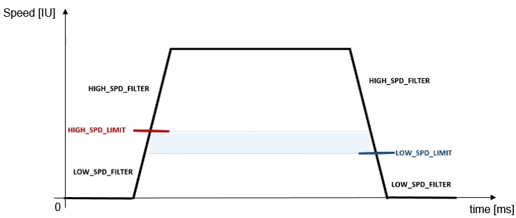
> HIGH_SPD_LIMIT
– represents the speed limit (in IU) from where the “HIGH_SPD_FILTER ” value is applied;
– by default, it is set to 0 IU, which means that the filter is inactive. To activate the filter, this parameter should be set to a value different than 0 IU, representing the threshold between the low speed and the high speed value;
– a stating value for this parameter is 20 rpm.
> LOW_SPD_LIMIT
– represents the the speed limit (in IU) from where the “LOW_SPD_FILTER ” value is applied;
– by default, it is set to 0 IU, which means that the filter is inactive. To activate the filter, this parameter should be set to a value different than 0 IU, that represent the threshold between the high speed and the low speed value;
– this parameter value must be smaller than the “HIGH_SPD_LIMIT” parameter value, because the algorithm uses this hysteresis, to determinate what filtration level should use;
– the max. recommended value for this parameter is 80% from the “HIGH_SPD_LIMIT” parameter value.
Remarks:
1) The relations between the drive internal units (IU) and the units in the International Measurement System are presented in the “Internal Units and Scaling Factors” help topic in EasyMotion Studio or Easy SetUp.
2) If the “HIGH_SPD_LIMIT” or parameter value is too high, the drive will start to ignore the good / real Hall pulses. As an effect, some speed jumps will appear and this may trigger the control error protection.
3) If the “LOW_SPD_LIMIT” parameter value is too high, the drive will start to ignore the good / real Hall pulses. As an effect, some speed jumps will appear (at low speeds) and the control error may trigger.
The graph below is a graphical representation of the above parameters description.
If the software filtration is not enough, some hardware filtration must be done. Below are few recommendations:
1. Connect the Hall sensors to the drive through a shielded cable and connect the shield to one of the drive GND terminals;
2. Mount an 100..120 Ohms resistor (function on the Hall sensor output parameters) between each Hall input and the drive +5V output.
3. Mount a 10 nF .. 20 nF capacitor between each Hall input and one of the drive GND terminals.
2. Speed Estimation in Low Speeds
The estimation algorithm measures the time duration of a predefined number of Hall transitions (using the encoder reading circuit) and estimates the speed as the ratio between a constant K and the measured time duration dT: Ω = K/dT.
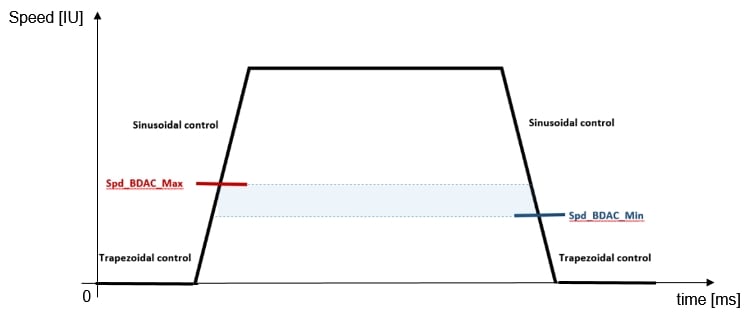
In low speeds (under 500 rpm) the estimation can’t be as good as in case of the high speeds, so the speed error will increase. As this is not a desired behavior, the firmware allows an automatic switch between the sinusoidal and trapezoidal control modes, improving the control in low speeds.
The mix between the trapezoidal and sinusoidal control modes assumes that the drive will control the motor using the trapezoidal commutation method, when the speed is between under the threshold value.
When the speed increases over the threshold, the commutation method will be automatically switched to sinusoidal.
When the motor decelerates and the speed drops below the threshold, the control mode will be switched back to trapezoidal.
This mixed control can be activated and set through the “Spd_BDAC_Max” and “Spd_BDAC_Min” parameters:
– the “Spd_BDAC_Max” parameter represents the speed threshold (in IU) used to switch the control from trapezoidal to sinusoidal (when the motor accelerates).
– the “Spd_BDAC_Min” parameter represents the speed threshold (in IU) used to switch the control from sinusoidal to trapezoidal (when the motor decelerates).
By default the “Spd_BDAC_Max” and “Spd_BDAC_Min” parameters are set to 0. This means the control is always sinusoidal.
If they will be set to 32767, the control will always be trapezoidal.
Setting the “Spd_BDAC_Max” and “Spd_BDAC_Min” to a value different than 0 IU or 32767 IU, will activate the mix between the trapezoidal and sinusoidal control modes.
The “Spd_BDAC_Min” parameter value must be a little bit smaller than the “Spd_BDAC_Max” because the algorithm uses this hysteresis, to determinate what control mode to use.
The mix between the sinusoidal and trapezoidal control modes has benefits when low seeds are required but it doesn’t help when the speed is around 0 rpm.
For this situations, there’s the ZEROSPDTLIM parameter. It defines the maximum time value, in prescaled processor clock pulses, after which, if less than “n” pulses (by default “n”=2) were captured, the speed is considered 0 IU.
By default, the ZEROSPDTLIM parameter is 65535. If need, it can be increased to 6553500.
General remark:
The parameters related to the Hall signals filtration or to the trapezoidal – sinusoidal mix are not available (as fields) in the EasyMotion Studio / Easy SetUp wizards. They need to be initialized with the needed value at the begging of the TML program or directly in the “parameters.cfg” file.
The “parameters.cfg” file is located in the application folder (by default: “C:\Program Files (x86)\Technosoft\ESM\Projects\Project_Name\Application_name“). It is a text file that can be edited with Notepad or Notepad++, for example
Notes:
1) Before modifying the parameters inside the “parameters.cfg” file, the EasyMotion Studio / Easy SetUp project must to be closed, to avoid the user parameters values overwriting with the default ones;
2) After the parameters values are set through the “parameters.cfg” file, it needs to be saved and closed. After reopening the EasyMotion Studio / Easy SetUp project, the new setup must be downloaded to the drive and then, the drive needs to be reset (a new setup became active only after the drive is reset);
3) The values inside the “parameters.cfg” file are expressed in IU (drive internal units).
4) If the trapezoidal – sinusoidal mix and the digital Hall signals filtration are used in parallel the “Spd_BDAC_Max” and “Spd_BDAC_Min” parameter values should be set a little bit lower the “HIGH_SPD_LIMIT” and “LOW_SPD_LIMIT” parameters values.
3. Error Amplification
The speed resolution, when using only the digital Hall sensors, is poor and many times even the speed controller gains are set to the maximum, the motor speed is still not following the reference. That’s why an error amplification is needed. This functionality is included in the firmware and can be activated by adding the following line at the end of the “parameters.cfg” file mentioned above.
• In case of iPOS2401, iPOS3602, iPOS3604 and iPOS4808 VX:
UINT SPD_ERR_AMPL @0x967F =8(0x0008)
• In case of iPOS4808, iPOS4850, iPOS8010, iPOS8020 and iMOTIONCUBE:
UINT SPD_ERR_AMPL @0×09C6 =8(0x0008)
The default value for the “SPD_ERR_AMP” parameter is 1 (no amplification) and it can be set function on the need amplification level.
Empirically was noticed that a good value for the “SPD_ERR_AMP” parameter is 8 or 10.