How Can We Help?
Details about the Incremental Encoder and Digital Halls configuration – Motor Setup [GB/CM]
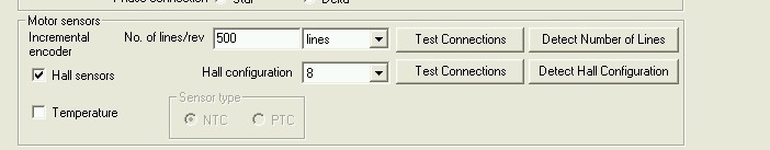
The incremental encoder and the Hall sensors are configured from the Motor Setup dialog in the EasySetUp/EasyMotion Studio software. Below is a short description of the Encoder Resolution and Direction Test and Hall configuration Detection Test. The Encoder Resolution and Direction Test is opened with the Detect Number of Lines button, while the Hall Configuration Detection Test opens when the Detect Hall Configuration button is pressed.
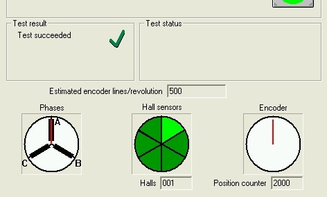
The Encoder Resolution and Direction Test measures the number of counts from the encoder during one motor shaft mechanical revolution and verifies if the positive count direction of the encoder matches the motor positive direction. The measured value is used to estimate the encoder resolution as the number of lines per revolution = number of counts / 4.
Remarks:
- The Encoder Resolution and Direction Test should be executed even when the encoder resolution is known, because if the positive direction of the motor doesn’t match the positive counting direction of the encoder, then the motor control will fail. If the positive direction of the motor doesn’t match the positive counting direction of the encoder, then swap 2 motor wires or encoder signals.
- The test can estimate correctly the following encoder resolutions: 64, 128, 256, 500, 512, 1000, 1024, 2000, 2048, 4000, 4096, 8000, 8192, 16000, 16384, 32000, 32768, 36000, 64000 and 65535.
- If the encoder resolution is not present in the previous list then first check if the number of counts (Position counter) is approximately 4 times higher than the encoder resolution, then set the No. of lines/rev to the resolution value specified in the datasheet of the encoder. If the differnece between the counts measured during the test and the encoder resolution x 4 is large (greater than 10 counts), increase the current test used during test and execute the test again.
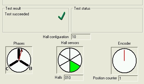
The “Hall Configuration Detection Test” determines the sequence of Hall sensors in relation to the motor phases (not the Hall number). The test moves the motor shaft in two specific positions and reads the signals from the Hall sensors. Based on this information, and knowing which motor phases were energized in the two positions, the test detects the Hall configuration. In total there are 12 posibilities (6 combinations of 2 polarities), which are numbered from 2 to 13.