|
Steps to follow:
| 1. | Setup the drives/motors for RS-485 communication |
| 2. | Mount on your PC an RS-485 interface board or an RS-232/RS-485 converter |
| 3. | Install on your PC an RS-485 software driver |
| 4. | Build the RS-485 network |
| 5. | Set EasyMotion Studio for communication via RS-485 with the drives/motors |
Step 1. Setup the drives/motors for RS-485 communication
| 1. | Power-Off the drive/motor |
| 2. | Disconnect the RS-232 serial cable if it is connected. |
| 3. | Put the RS-232/RS-485 switch (or solder-joint) on position RS-485. |
| 4. | Choose a different axis ID for each drive/motor and also different from the axis ID of PC (which is set by default at 255). The drives/motors axis ID is set at power on using the following algorithm: |
| a. | With the value read from the EEPROM setup table containing all the setup data |
| b. | If the setup table is invalid, with the last axis ID value read from a valid setup table |
| c. | If there is no axis ID set by a valid setup table, with the value read from the hardware switches/jumpers for axis ID setting |
| d. | If the drive/motor has no hardware switches/jumpers for axis ID setting, with the default axis ID value which is 255. |
Remark: If your drive/motor has no hardware switches/jumpers for axis ID setting, you must program the desired axis ID in the drive/motor setup table. You can do this operation from Easy Motion Studio – the setup part of an application, where you can select the axis ID to be saved in the drive/motor setup table from the EEPROM. Use the RS-232 communication to download the setup data.
Step 2. Mount on your PC an RS-485 interface board or an RS-232 / RS-485 converter
Usually, the standard PCs do not provide an RS-485 interface. In order to use EasyMotion Studio to communicate with your drives/motors via RS-485, you need to mount on your PC an RS-485 interface. This interface can be an add-in board or an RS-232 to RS485/RS-422 converter connectable to the standard serial ports of the PC.
Technosoft provides, if needed, RS-232 to RS-485 converters as well as other accessories for RS-485 networking. If you intend to use your own RS-232 to RS-485/RS-422 converter, please note that this should use the RTS line for transmission control, with the RTS signal active high (+5 to +12V) to enable the PC transmission and disable reception. These conditions are usually met by most of the RS-232 to RS-485/RS-422 converters. A typical example of an RS-232 to RS-485 converter, you can buy on the shelf is the model IC-485AI from ATEN (http://www.aten-usa.com/) that can be used either as RS-232 to RS-485 converter or as RS-232 to RS-422 converter. To use this model as an RS-232 to RS-485 converter, you need to:
| • | Set the switch DCE/DTE on position DCE |
| • | Set the switch T-ON R-ON / T-RTS R-/RTS / T-RTS R-ON on position T-RTS R-/RTS |
| • | Connect the RS-485 signal +A to converter inputs T+ and R+, the RS-485 signal –B to converter inputs T- and R- and the RS-485 ground to the converter shield |
Remark: If you use a non-isolated converter like model IC-485S from ATEN, connect the RS-485 ground to the PC serial connector ground
Important: the RS-232 to RS-485 converter must free the RS-485 line immediately after the last stop bit is transmitted, without other delays.
Step 3. Install on your PC an RS-485 software driver
In order to use an RS-232 to RS-485 converter with RTS control of the PC transmissions, you need to install on your PC an RS-485 serial driver. This driver should automatically activate the RTS line during the PC transmissions.
Remark: You can find more information about how to setup and use the RS-485 communication on the application notes from the Technosoft web page (http://www.technosoftmotion.com/B2000/AllPages/OEM_PROD_App_Notes_20.htm)
Step 4. Build the RS-485 network
Each drive/motor manual shows how to do the connections in order to build an RS-485 network.
Step 5. Set EasyMotion Studio for communication via RS-485 with the drives/motors

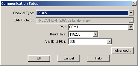
| 1. | Select menu command “Communication | Setup” |
| 2. | Select at “Channel Type” RS-485 |
| 3. | Select at “Port” the serial port of your PC, where you have connected the serial cable. By default COM1 is selected. |
| 4. | Select the desired baud rate from “Baud Rate” |
| 5. | Select at “Axis ID of PC is” an address for the PC. By default the value proposed is 255. Attention! Make sure that all the drives/motors from the network have a different address. |
If the RS485 interface mounted on PC works properly, you’ll see displayed on the status bar of the EasyMotion Studio the text “Online” and the axis ID of the PC.
See also:
RS-485 Communication Troubleshoots
Advanced Communication Setup
Communication Setup
| 