Introduction
One of the most critical steps in motor control applications is ensuring the system can identify the motor’s exact position before starting the working cycle. This can be achieved on every power-on or reset through a process known as a homing. It allows the drive to position the motor to a reference point, called the home position, even in the absence of an absolute encoder.
Our drives integrate a wide selection of homing routines, with support for 35 routines based on the CiA DS402 standard (CANopen device profile for motion control).
This variety gives users the flexibility to choose the best option for their system, whether it’s a basic method or a more complex one. In this article, we’ll go through the different homing routines our drives support and describe them.
Homing routines
When setting up a homing routine, the user must select the homing method and configure several key parameters. These include:
- home position
- acceleration and deceleration rates
- high speed – used for the initial motion to find the home position
- low speed – used after the home sensor transition, when the home position must be found with high precision
- current threshold and current threshold time – used by the homing routines based only on the mechanical limit detection (no external sensors)
This article will give a general description of the pre-defined homing routines. There are various methods to achieve the home position using the four available sources for the homing signal: limit switches (negative and positive), home switch (input IN0) and encoder index pulse.
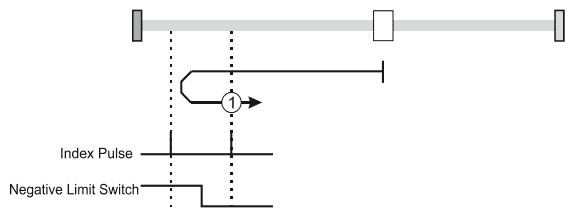
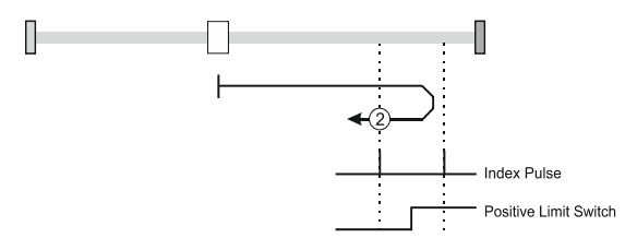
Homing on the Limit Switches and Index Pulse
The motor starts using the “high speed” setting toward the selected limit switch. If the motor is already on the limit or after it is reached, the drive will reverse the motion, moving away from the limit with the “low speed” setting. The home position is finally set at the first index pulse encountered after the limit switch is becoming inactive. This homing mode can be configured to use either of the positive limit switch or negative limit switch (the drive will automatically handle the correct movement direction).
Homing on the Positive Home Switch and Index Pulse.
Similar to the previous type of homing method – only this time a dedicated “home switch” will be used instead of the limit switches.
The home position is set on the index pulse either after home switch high-low transition or after home switch low-high transition – depending on the selection. The diagram shows two initial movements for each type of method. This is because the initial direction of movement is dependent on the state of the home switch.
In all cases after home switch transition, the speed of the movement is slow.

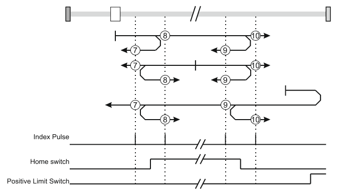
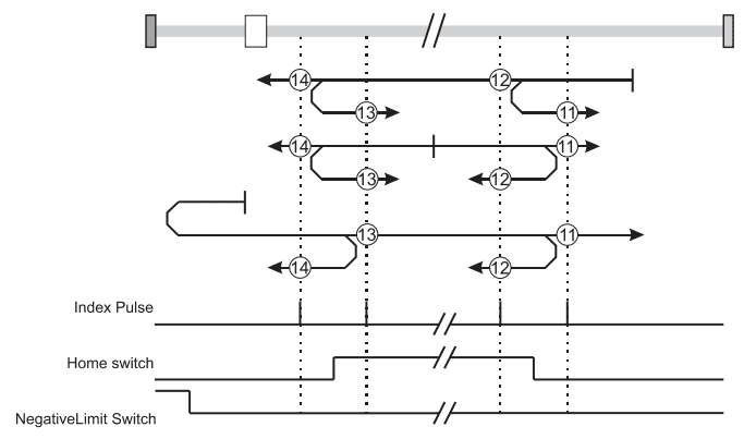
Homing on the Home Switch using Limit Switches and Index Pulse.
These methods use a home switch that is active over only a portion of the travel distance; in effect the switch has a ‘momentary’ action as the axle’s position sweeps past the switch. The initial direction of movement is configurable via the selected homing number, except the case when the home switch is active at the start of the motion (initial direction of motion is dependent on the edge being sought – the rising edge or the falling edge). The home position is set at the index pulse on either side of the rising or falling edges of the home switch, as shown in the following two diagrams. If the initial direction of movement leads away from the home switch, the drive will reverse on encountering the relevant limit switch (user selectable via the homing number).
Homing without an Index Pulse
These methods are similar to the ones presented already, except that the home position will no longer be set on the index pulse but only on the relevant home or limit switch transitions.
Homing only on the Index Pulse
During these procedures, the motor will move only at slow speed. The home position is set at the index pulse found in the selected direction.
Homing on the Current Position
There is no motor movement involved in this case – the current motor position is set with the value of home position.
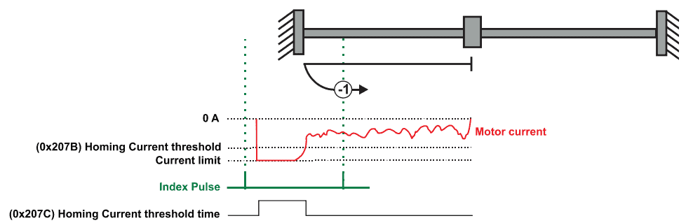
Homing on the Mechanical Limit and Index Pulse
These methods were created by us based on the experience we had with our customers in cases where there was either no physical sensor present or all the drive digital inputs were used already. They rely on one of the 2 ways of detecting when the mechanical limit is reached by the motor:
- Based on motor current increase
This method applies to all closed loop motor configurations. It does not apply to Stepper Open Loop configurations. The motor will start to move in the selected direction until the “Current threshold” is reached for a specified amount of time. This relies on the controller response to the ever increasing position error (the motor will be standing, pushing against the limit, while the reference will continue to increase) – the drive will increase the motor torque in an effort to reduce the position error. When the mechanical limit is found in this way, the motor will reverse and stop at the first index pulse, where the home position will be set.
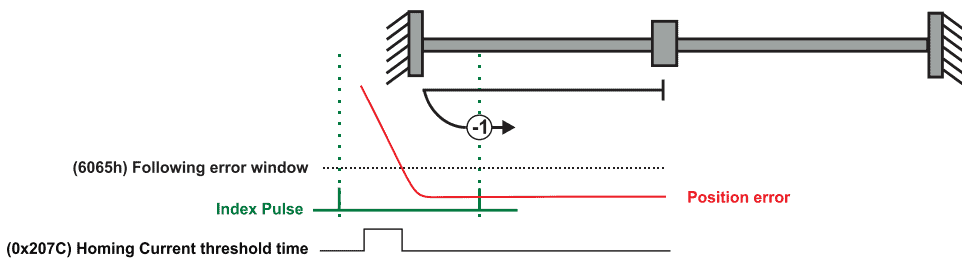
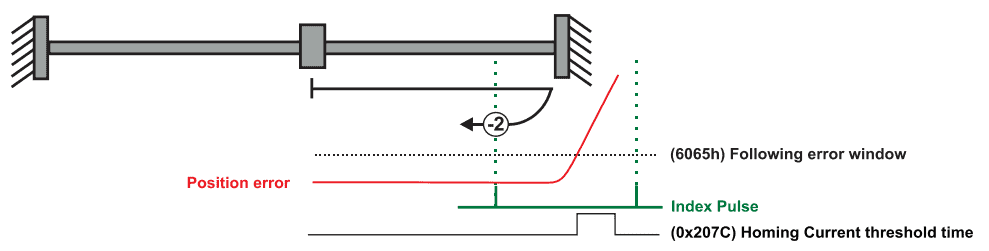
- Based on step loss detection
This method applies only to Stepper Open Loop with Encoder on motor or Encoder on Load. It does not apply to Closed loop configurations or Stepper Open Loop without an incremental encoder present. This homing method will detect a Position control error when reaching the mechanical limit. The rest of the homing method is identical to the previous case, only the way the mechanical limit is detected is changed because in case of open loop operation the motor current is always constant and not dependent on the position error.
Homing on the Mechanical Limit without an Index Pulse
Finally, these methods are similar to the previous ones, except that the home position is not dependent on the index pulse but only on the home position specified by the user. After the mechanical limit is found, the motor will move away from the limit with the distance indicated by the user via the “home position” variable and then set the motor position to that value.
Conclusion
Technosoft drives feature an extensive range of homing routines based on the CANopen CiA 402 standard and some special routines created by us based on our field experience, offering flexibility for a wide variety of applications. Whether the system requires standard edge-detection methods, limit switch-based routines, or more advanced routines involving home switch, index pulse and direction reversals, our drives provide precise and reliable homing methods. The integration of those homing routines is very easy using our EasyMotion Studio II application and only requires the user to select the homing parameters and the homing method.
Even like this, our drives are not limited to the homing methods presented – you can further customize any of the existing ones or create completely new homing procedures for your applications with the help of TML (Technosoft Motion Language).
Contact our team today!