- Introduction
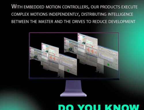
Using EasyMotion Studio II, the performance of Technosoft drivers can be monitored along with receiving general data and any possible errors that might be triggered. These real-time features give also an elegant way of observing the driver’s TML program flow making its troubleshooting a simple process.
These graphical tools are divided into 3 categories: Control Panels, Scope and Logger – together, they offer a full blend between “quantity” and “quality”.
Starting with the Control Panels, which are more on the “quantity” side where you can get big amounts of data from the drive (the only limit being the communication speed of the channel used) but without being able to synchronize this data with the internal control loops, we then have the Scope, a digital oscilloscope that offers the possibility of visualizing on-line the exact evolution of up to 4 drive parameters / variables thus being a middle ground between quantity and quality and finally we have the Logger, the most precise tool that allows the user to record and investigate the evolution at the level of individua control loops. The trade off here is that the data recorded in this way is limited to the amount of available RAM memory of the drive.
- Control Panel
The Control Panel is a tool in which the user is able to visualize the value of any parameter and any status register, as well as sending commands and plotting graphs.
EasyMotion Studio II comes with a set of predefined Control Panels and the user has the option to modify them if needed or even create new ones according to their specific needs.
Below are some example of these ready made panels.
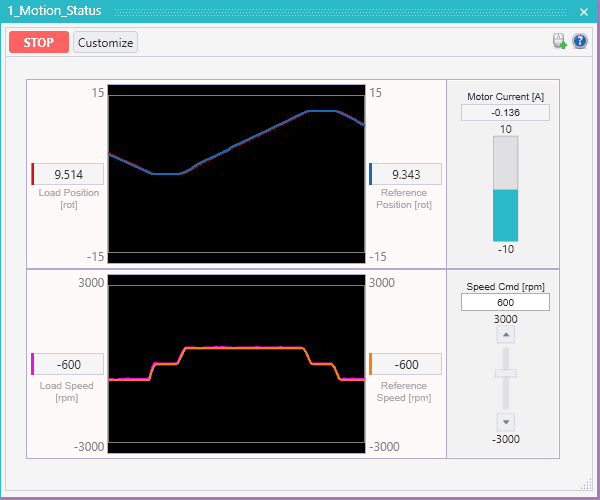
2.1 Motion_Status Control Panel
The “1_Motion_Status” Control Panel displays some general information regarding the motor dynamics, such as graphs for the Speed, the Load Position and their References, as well as the Motor Current and a slider for changing the Speed Command.
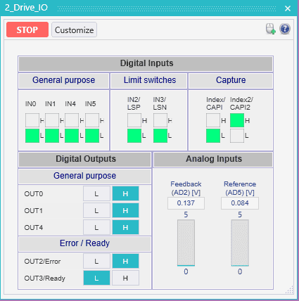
2.2 Drive_IO Control Panel
The “2_Drive_IO” Control Panel provides information of all the digital Inputs/Outputs and Analogue inputs (Feedback and Reference) values. The state of the digital Inputs/Outputs is dependent on their type (NPN or PNP). Moreover, the state of the digital outputs can be directly changed by the user using this Control Panel.
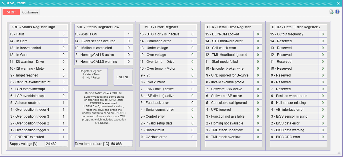
2.3 Drive_Status Control Panel
The “5_Drive_Status” offers information on some of the special registers, such as the:
– Status Register High and Low (SRH & SRL): containing key information regarding the drive/motor, such as: Axis ON/OFF state (indicates if the motor is energized and the control loops are active or not); the Fault status; the ENDINIT state; (done upon powering up the Logic supply of the drive, indicates if the firmware’s internal initialization is complete).
– Motion Error Register (MER): is the register containing all the error conditions. The user is able to determine the cause of any Fault by checking which bit of this register is set.
– Detailed Error Register (DER / DER2): they provide additional details regarding the some of the bits signaled in MER.
This Control Panel also provides information on the DC voltage supply value read by the drive, and the temperature of the drive.
2.4 Control Panel customization
A powerful feature of the Control Panels is their customization, the user is able to customize any of the predefined ones or create a new one.
The Customize button is found in the top left corner of any CP and it will reveal the items available for the creation / modification as well as switch the active panel into the customize mode:
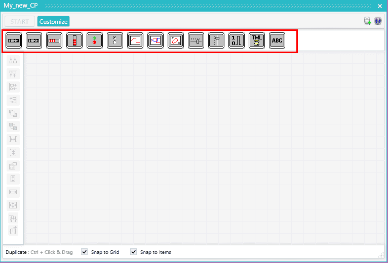
To add an object, it must be dragged onto the CP window. The available options are as follows: show value, gauges, inputs and outputs displays, scopes, sliders, bit value displays and TML script buttons.
If the user has multiple applications in an EasyMotion Studio II project (each application corresponding to its own drive), the user can query the variables of any drive in any of the active applications. This can be done by selecting from which application they want to see the variable:
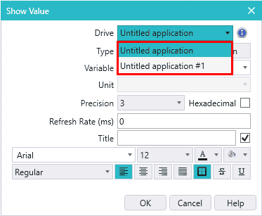
Remark: this feature is valid if the drives are connected in a CANbus network, regardless of the protocol used (CANOpen / TMLCAN) and the communication channel used for EasyMotion Studio II (USB / RS-232 / CAN)
3 Scope
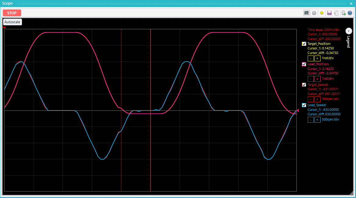
The Scope acts as a digital Oscilloscope and is a powerful tool for monitoring exact changes of up to 4 variables, having two time-based operating modes:
– Normal, which can have a time/div sample as low as 1ms and can be configured to have different types of trigger events (based on a variable selected to be plotted and upon a rising or falling edge of the source signal)
-Roll, which will continuously update the waveforms, at the cost of a larger time scale to ensure that the reception data from the drive is correctly done.
- Logger
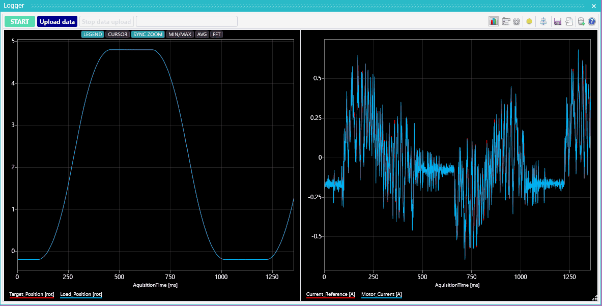
The Logger is a tool designed for most precise data acquisition. The data logging is triggered by the user (upon pressing the “Start” button) and it will be stored internally in a RAM buffer (the size of the buffer varies depending on the drive/motor memory available for data logging), the number of data points being dependent on the number of selected variables.
Depending on the variables recorded, the user has also the option to configure the measurement time base at which the data is being sampled, that is the slow loop (default 1ms) or the fast loop (default 0.1ms) and the periodicity of the sampling.
Once the recording is finished, the user has to instruct the Logger to read that data from the drive, by pressing the “Upload data” button. This will plot all the variables recorded on a graph similar to control panel / scope but giving more processing freedom to the user:
For example, zooming in on the area pointed by the red arrow and activating the “cursor” option, the values can be observed in a precise manner (as well as the visualizing each moment where the samplings are done):
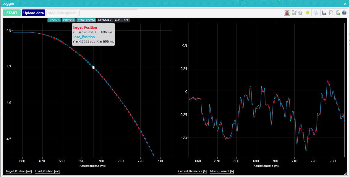
Unlike the Scope, the Logger can log more than 4 variables at a time, but since the buffer space is equally divided between all the variables, this will result in a shorter recording time therefore the user must take into account how many variables need to be logged in the same time (or make a compromise on the precision and increase the sampling time base).
- Conclusion
Having a way of real-time monitoring the drive/motor performance helps the user identify if there are any issues within the TML programming or if the CANopen/EtherCAT commands of the master were correctly received/executed by the drive, as well as determining the reasons for the drive entering a Fault status and even help a lot in the tuning process.
Contact our team today!
