UPGRADE is a 16-bit status register, defining new options and extended features that are activated when their corresponding bits are set.
TML Address: 0x0857
Contents. UPGRADE information is structured as follows:
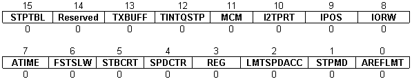
Bit 15 STPTBL. Setup table
0 = |
Valid setup table is not required |
1 = |
Valid setup table is required |
Bit 14 Reserved
Bit 13 TXBUFF. CAN-bus transmit buffer length
0 = |
The length of CAN-bus transmit buffer is 1 messages |
1 = |
The length of CAN-bus transmit buffer is 5 messages |
Bit 12 TINTQSTP. TML time interrupt/quickstop
0 = |
Disable |
1 = |
Enable TML time interrupt and quickstop mode when a limit switch is reached |
Bit 11 MCM. Motion complete mode
0 = |
Motion complete set when the position reference arrives at the commanded position |
1 = |
Motion complete set when the position feedback arrives at the commanded position and remains in a settle band for a preset stabilize time interval |
Bit 10 I2TPRT. I2T protection
0 = |
One I2T protection common for drive and motor |
1 = |
Two I2T protections, one for drive and the other for the motor |
Bit 9 IPOS. Initial positioning mode
0 = |
Standard – wait time per phase up to 1s |
1 = |
Extended – wait time per phase up to 635s |
Bit 8 IORW. I/O lines read/write
0 = |
Simultaneous read /write of 4 general purpose inputs/outputs |
1 = |
Simultaneous read 4 general-purpose inputs and 3 dedicated inputs: Enable, LSP and LSN. Simultaneous set 4 general-purpose outputs and 2 dedicated outputs: Ready and Error. |
Bit 7 ATIME. Absolute time start
0 = |
After instruction ENDINIT |
1 = |
After power on |
Bit 6 FSTSLW. Position/speed control mode
0 = |
Position/speed control in slow loop |
1 = |
Position/speed control in fast loop |
Bit 5 STBCRT. Standby current for step motors
0 = |
Disable |
1 = |
Enable |
Bit 4 SPDCTR. Speed control error protection
0 = |
Common with position control error protection |
1 = |
Separate control error protection for position and speed |
Bit 3 REG. Registration mode
0 = |
Disabled |
1 = |
Enabled |
Bit 2 LMTSPDACC. Maximal speed/acceleration in motion modes: external, electronic gearing and electronic camming
0 = |
Unlimited |
1 = |
Limited |
Bit 1 STPMD. Stop mode for steppers
0 = |
Disabled |
1 = |
Enabled |
Bit 0 AREFLMT. Analogue reference
0 = |
Symmetrical, only positive or only negative |
1 = |
Separately programmable upper and lower limits |