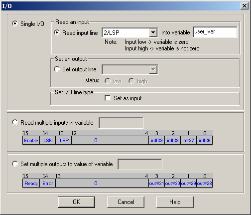
The “I/O” dialogue allows you to program the following operations with the digital inputs and outputs:
| • | Read and save the status of a digital input into a variable |
| • | Set low or high a digital output |
| • | Read and save the status of multiple digital inputs into a variable |
| • | Set multiple digital outputs according with the value of variable |
The digital inputs and outputs are numbered: #0 to #39. Each intelligent drive/motor has a specific number of inputs and outputs, therefore only a part of the 40 I/Os is used. The I/O numbering is common for all the products; hence each product has its own list of available I/Os. This is not an ordered list. For example, a product with 4 inputs and 4 outputs can use the inputs: #36, #37, #38 and #39 and the outputs #28, #29, #30 and #31.
If you want to read the status of an input:
| 1. | Select Single I/O, Read input line, choose the desired input from the list of available inputs and provide the name of an integer variable where to save the input status |
| 2. | Check Set as input if the input selected may also be used as an output (i.e. the input line number occurs in the outputs list too). Do this operation only once, first time when you use the input. Omit this check if the drive/motor has the inputs separated from the outputs (i.e. all have different line numbers) |
| 3. | Press OK |
When this TML command is executed, the variable where the input line status is saved, becomes:
| • | Zero if the input line was low |
| • | Non-zero if the input line was high |
Remark: Check the drive/motor user manual to find if the input line you are reading is directly connected or is inverted inside the drive/motor. If an input line is inverted, the variable where the input line is saved is inverted too: zero if the input is high (at connectors level), non-zero if the input is low (at connectors level).
If you want to set an output low or high:
| 1. | Select Single I/O, choose Set output line, select the desired output from the list of available outputs and choose the output level: low or high |
| 2. | Check Set as output if the output selected may also be used as an input (i.e. the output line number occurs in the inputs list too). Do this operation only once, first time when you use the output. Omit this check if the drive/motor has the inputs separated from the outputs (i.e. all have different line numbers) |
| 3. | Press OK |
Remark: The TML code generated takes into account the possibility to have outputs inverted inside the drive/motor. This information, provided by the setup data, is used to inverse the output command logic: getting the output high (at connectors level) means setting the output low and to getting the output low (at connectors level) means setting the output high
Check Read inputs in variable to read simultaneously more inputs and specify the name of an integer variable where to save their status. The inputs are:
| • | Enable input – saved in bit 15 |
| • | Limit switch input for negative direction (LSN) - saved in bit 14 |
| • | Limit switch input for positive direction (LSP) - saved in bit 13 |
| • | General-purpose inputs #39, #38, #37 and #36 – save din bits 3, 2, 1 and 0 |
The bits corresponding to these inputs are set as follows: 0 if the input is low and 1 if the input is high. The other bits of the variable are set to 0.
Remark: If one of these inputs is inverted inside the drive/motor, the corresponding bit from the variable is inverted too. Hence, these bits always show the inputs status at connectors level ( 0 if input is low and 1 if input is high) even when the inputs are inverted.
Check Set multiple outputs to a value of variable to set simultaneously more outputs with the value of the specified variable. The outputs are:
| • | Ready output – set by bit 15 |
| • | Error output – set by bit 14 |
| • | General-purpose outputs: #31, #30, #29, #28 – set by bits 3, 2, 1, and 0 |
The outputs are set as follows: low if the corresponding bit in the variable is 0 and high if the corresponding bit in the variable is 1. The other bits of the variable are not used.
Remark: If one of these outputs is inverted inside the drive/motor, its command is inverted too. Hence, the outputs are always set at connectors level according with the bits values (low if bit is 0 and high if bit is 1) even when the outputs are inverted.
CAUTION: Do not use Set multiple outputs to a value of variable if any of the 6 outputs mentioned is not on the list of available outputs of your drive/motor. There are products that use some of these outputs internally for other purposes. Attempting to change these lines status may harm your product.
OK: Close this dialogue and save the motion sequence in your motion sequence list.
Cancel: Close this dialogue without saving anything in your motion sequence list.
Help: Open this help page.
See also: