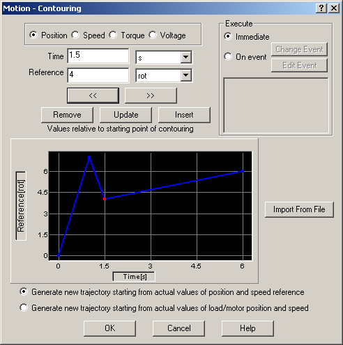
The “Motion - Contouring” dialogue allows you to program an arbitrary contour via a series of points. Between the points, linear interpolation is performed, leading to a contour described by a succession of linear segments. The contouring mode may be executed only from a TML program. You can’t send contouring points from a host via a communication channel, like in the case of the PT mode. Depending on the control mode chosen, four options are available:
| • | Position contouring – the load/motor is controlled in position. The path represents a position reference |
| • | Speed contouring – the load/motor is controlled in speed. The path represents a speed reference. |
| • | Torque contouring – the motor is controlled in torque. The path represents a current reference. |
| • | Voltage contouring – the motor is controlled in voltage. The path represents a voltage reference. |
Each contour point is defined by 2 values: the reference and the time. The contouring mode has been foreseen mainly for setup tests. However, you can also use the position contouring and the speed contouring for normal operation, as part of your motion application. You can switch at any moment to and from these 2 modes. The torque contouring and the voltage contouring have been foreseen only for setup tests. The torque contouring may be used, for example, to check the response of the current controllers to different input signals. Similarly, the voltage contouring may be used, for example, to check the motors behavior under a constant voltage or any other voltage shape.
Choose
Position for a position contouring,
Speed for a speed contouring,
Torque for a torque contouring
Voltage for a voltage contouring.
Remarks:
| • | Position contouring option is disabled if the drive/motor is not setup for position control |
| • | Speed contouring option is disabled if the drive/motor is not setup for speed control. This includes the case when position control is performed without closing the speed loop |
| • | Torque contouring option is disabled for stepper drives working in open loop |
In the position contouring and the speed contouring the starting point has always the coordinates (0,0) and corresponds to the moment when the contouring mode is activated. Therefore all the segments values (time and reference) are relative to the starting point of the contouring. For example, lets suppose that a position contouring sequence has one segment with coordinates (1s, 10 rot) and the absolute position is 20 revolutions (initial position when the position contouring is activated). During the contour segment execution, the motor moves 10 revolutions in 1 second and stops on absolute position 30 revolutions.
In the torque contouring and voltage contouring the starting point has by default the initial value 0. However, you can also start with a different value, by setting in the first point a non-zero reference at time = 0.
You can introduce the contouring points in 2 ways:
| • | One by one, by setting for each point its Time and Reference values. Select the measuring units from the list on the right. The graphical tool included, will automatically update the contour as you introduce each point. A red spot, indicates the active point. Use buttons: Remove, Update, Insert, << and >> to navigate between the points and modify them. |
| • | With Import From File to insert a set of contouring points previously defined. The file format is a simple text with 2 columns separated by space or tabs representing from left to right: time and reference values. The number of rows gives the number of points |
Select Generate new trajectory starting from actual values of position and speed reference if you want the reference generator to compute the contour profile starting from the actual values of the position and speed reference. Select Generate new trajectory starting from actual values of load/motor position and speed if you want the reference generator to compute the contour profile starting from the actual values of the load/motor position and speed. When this option is used, at the beginning of each new contour profile the position and speed reference is updated with the values of the load/motor position and speed. Use this option for example at recovery from an error or any other condition that disables the motor control while the motor is moving. Updating the reference values leads to a “glitch” free recovery because it eliminates the differences that may occur between the actual load/motor position/speed and the last computed position/speed reference (before disabling the motor control).
Remark: In open loop control of steppers, this option is ignored because there is no position and/or speed feedback.
Choose Execute Immediate to start the contour profile immediately when the motion sequence is encountered. Choose Execute On event to start the motion when a programmable event occurs. Click Change Event to select the event type or Edit Event to modify the parameters of the selected event (see Events for details).
OK: Close this dialogue and save the motion sequence in your motion sequence list.
Cancel: Close this dialogue without saving the motion sequence in your motion sequence list.
Help: Open this help page.
See also:
Contouring – TML programming details
Contouring – TML Instructions and Data
Internal Units and Scaling Factors