Syntax
VAR16D = IN#n |
read input #n into VAR16D |
VAR16D = INPUT1, ANDm |
read inputs IN#25 to IN#32 into VAR16D with ANDm |
VAR16D = INPUT2, ANDm |
read input IN#33 to IN#39 into VAR16D with ANDm |
VAR16D = INPORT, ANDm |
read Enable, LSP, LSN and IN#36 to IN#39 into VAR16D with ANDm |
| Operands |
Var16D: integer variable
IN#n : the source is input n (0=<n<=39)
INPUT1: the source is inputs #25 to #32
INPUT2: the source is inputs #33 to #39
ANDm: a 16-bit mask for filtering the inputs. A logical AND is performed between the inputs read and the ANDm mask
INPORT: the source is 7 inputs: Enable, LSP, LSN, #39, #38, #37 and #36
![]()
Binary code


| Description | Read digital input(s) and assign a 16-bit TML variable with their value. When a single input is read (IN#n), the destination variable is set to 0 when the input is 0 (low) and to a non-zero value when the input is 1 (high). When multiple inputs are read with INPUT1 or INPUT2, each of the 8LSB of the destination variable shows one input status: 0 – input is 0 (low), 1 – input is 1 (high) after passing through the ANDm mask. The inputs are assigned from bit 0 to 7 in ascending order (IN#25 – bit 0, IN#26 – bit 1, etc.). INPORT works like INPUT1 / INPUT2 except the bit assignment in the destination variable: Enable – bit 15, LSN – bit 14, LSP – bit 13, #39 – bit 3, #38 – bit 2, #37 – bit 1, #36 – bit 0. |
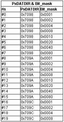
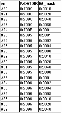
In TML the I/O lines are numbered: #0 to #39. Each product has a specific number of inputs and outputs, therefore only a part of the 40 I/O lines is used. The I/O numbering is common for all the products; hence each product has its own list of available I/Os.
These instructions use a 9-bit short address for the destination variable. Bit 9 value X specifies the destination address range:

Execution Read input(s) and set their status in reserved bits from the destination


Example1
int Var1;
...
Var1 = IN#14;
Before instruction |
|
After instruction |
||
IN#14 status |
1 |
|
IN#14 status |
1 |
Var1 |
x |
|
Var1 |
0x0040 |
|
|
|
Bit#6 of Var1 has logic value of IN#14. Remaining bits are set to 0. |
|
Example2
int Var1;
...
Var1 = INPUT1, 0x00E7;
Before instruction |
|
After instruction |
||||||||||||||||
IN# |
32 |
31 |
30 |
29 |
28 |
27 |
26 |
25 |
|
IN# |
32 |
31 |
30 |
29 |
28 |
27 |
26 |
25 |
Status |
0 |
1 |
1 |
0 |
1 |
1 |
0 |
1 |
|
Status |
0 |
1 |
1 |
0 |
1 |
1 |
0 |
1 |
Var1 |
x |
|
Var1 |
0x0065 |
||||||||||||||
IN# |
32 |
31 |
30 |
29 |
28 |
27 |
26 |
25 |
Bitwise operation |
Inputs status |
0 |
1 |
1 |
0 |
1 |
1 |
0 |
1 |
|
And_Mask |
1 |
1 |
1 |
0 |
0 |
1 |
1 |
1 |
|
Var1 |
0 |
1 |
1 |
0 |
0 |
1 |
0 |
1 |
Example3
int Var1;
...
Var1 = INPUT2, 0x00E7;
Before instruction |
|
After instruction |
||||||||||||||
IN# |
39 |
38 |
37 |
36 |
35 |
34 |
33 |
|
IN# |
39 |
38 |
37 |
36 |
35 |
34 |
33 |
Status |
1 |
0 |
0 |
1 |
1 |
0 |
1 |
|
Status |
1 |
0 |
0 |
1 |
1 |
0 |
1 |
Var1 |
x |
|
Var1 |
0x0085 |
||||||||||||
IN# |
39 |
38 |
37 |
36 |
35 |
34 |
33 |
Bitwise operation |
Inputs status |
1 |
0 |
0 |
1 |
1 |
0 |
1 |
|
And_Mask |
1 |
1 |
0 |
0 |
1 |
1 |
1 |
|
Var1 |
1 |
0 |
0 |
0 |
1 |
0 |
1 |
Example4
int Var1;
...
Var1 = INPORT, 0xE00F;
Before instruction |
|
After instruction |
||||||||||||||
IN# |
Enable |
LSN |
LSP |
39 |
38 |
37 |
36 |
|
IN# |
Enable |
LSN |
LSP |
39 |
38 |
37 |
36 |
status |
1 |
0 |
1 |
1 |
0 |
1 |
1 |
|
status |
1 |
0 |
1 |
1 |
0 |
1 |
1 |
Var1 |
X |
|
Var1 |
0xA00B |
||||||||||||